
User's Manual


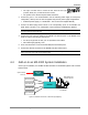


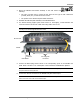
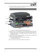
Table Of Contents
- Preface Material
- Product Certifications
- Company Certification
- Introduction to the MA-860 System
- Element Descriptions
- Infrastructure Preparation
- Installation
- Power-up and Provisioning the Unit
- Appendix

Installation
MA-860 Installation and Configuration Guide 22
• The type of screws used to mount the unit must suit the type of wall construction
(cement, bricks, etc.) so that the mount is secure.
• The position of the APs and required cable connections.
2. Connect the power. It is recommended to use the following power supply for local power
configuration, where p
ower can also be supplied using remote power supply configurations
:
• Dedicated power supply (i.e. LPS-48-66W – refer to the Power Supplies Manual)
3. Connect the 802.11a/b/g Access Points to the corresponding ports on the MA-860 rear
panel.
Refer to section 1.3 for a description of the connections and distribution patterns.
NOTE: It is recommended to RESET the unit by removing and reinserting the power connector on the
front panel after connecting the APs.
4. Connect the coax antenna cables to the MA-860 unit antenna ports on the MA-860 front
panel according to the following instructions:
• Use 50 Ω, N-type male to male, 1/2” or 3/8” Plenum coax cables
• Max cable length (typically): 150’
5. Fit 50 ohm terminators on all unconnected SMA, AP and antenna ports.
6. Connect the network connection to the MA-860 rear panel network port.
NOTE 1: It is recommended to record the location of the units according to the MAC addresses on the
sticker at the rear of the units near the Ethernet port.
4.4 Add-on to an MA 1000 System Installation
In this type of installation, the MA-860 and MA 1000 RHU are assembled together with a
bracket
between them.
MA 1000
RHU
MA 860
802.11a/b/g AP
802.11a/b/g and
Cellular signals
Optic Cellular
services
802.11a/b/g AP
802.11a/b/g AP
802.11a/b/g AP
SCU
Passive Antennas
and WCEs
WCE
Figure 4-2 MA-860 as Add-On to MA 1000 System[MP9]