
User's Manual


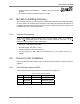
Table Of Contents
- Preface Material
- Product Certifications
- Company Certification
- Introduction to the MA-860 System
- Element Descriptions
- Infrastructure Preparation
- Installation
- Power-up and Provisioning the Unit
- Appendix

Infrastructure Preparation
MA-860 Installation and Configuration Guide 18
• LPS-48-100W (recommended)[MP7] - combined with the MA 1000 RHU. Feeds both
modules
• In-line power supply connected through a coax cable.
3.4 MA-860 In-building Antennas
The in-building antennas are connected to the coaxial cable distribution system by jumper cables
at various points. The antennas will be mounted on the ceiling tiles and should be exposed. All
in-building antenna installations will be such that it will not interfere with indoor traffic and will
not enable any person to touch the antennas.
3.4.1 Antenna Connections
NOTE: If the MA-860 system installation does not include cellular service, it is required to
connect 50Ω termination points to each of the remote connectors in the unit. A 50 Ω
termination is also required on each unused AP port.
• 50 Ω, 1/2” or 3/8” Plenum coax cables
• Max cable length: 150’ (
future – 200’)
• 50 ohm terminator on unused connections
• For short jumpers (to MRC antenna ports): RG223 2 ft or 10 ft male-to-male coax
jumpers
3.5 Access Points Installation
This section lists the vendor approved APs and the procedures required to prepare the APs for
operation.
3.5.1 List of Vendor Approved APs
The following vendor Access Points have been verified and FCC approved.
Table 3-3. Approved Access Points
FCC ID Model Functionality Access Points
MA-MA-860 CISCO 1232, 1242
MA-MA-860 Aruba AP 60. 61, 70
MA-MA-860 Colubris AP