
User's Manual


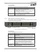
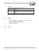


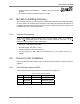
Table Of Contents
- Preface Material
- Product Certifications
- Company Certification
- Introduction to the MA-860 System
- Element Descriptions
- Infrastructure Preparation
- Installation
- Power-up and Provisioning the Unit
- Appendix

Element Descriptions
MA-860 Installation and Configuration Guide 12
Front Panel LEDs
The front panel contains two LEDs, described in the following table.
Front Panel LEDs Description
Run Internal operation and channel operation status:
o Green constant – unit performing antenna auto-discovery. This
happens only upon power-up.
o Green blinking – Auto-discovery completed and unit OK.
o Off – fault detected in unit (if power is supplied)
PWR Green – Power OK.
Off – no power supplied to the unit.
2.1.2 Rear Panel Port Connections and LEDs
The rear panel contains the 802.11a/b/g AP connections, Ethernet connection for remote
management and antenna sensing connector.
Figure 2-2. MobileAccess MA-860 Rear View
Rear Panel Ports
The following table describes the rear panel ports.
Rear Panel Ports Description
802.11b/g APs APs 802.11b/g input connections. (See LED descriptions in the
following table).
NOTE: To be terminated with 50 ohm terminations when not in use.
802.11a APs APs 802.11a input connections.
NOTE: To be terminated with 50 ohm terminations when not in use.
From Add-on to
Control
Relevant only when MA-860 is converged with another MA system
remote unit (RHU 1000, RHU WiMAX
[MP6]. Connects to RHU 1000
rear panel Control connector. Routes the antenna sensing
(indication of whether antenna is present) to the RHU for
monitoring via the management application. (RHU Version 3.1
and higher).
Ethernet port Connection to network for configuration and management
through a WEB browser.
Ethernet port
Antenna sense
connection
802.11a/b/g AP connections
MAC Address