
User's Manual


MA 850 Front and Rear Panels
MA 850 Installation and Configuration Guide 3
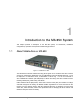
1.2 MA 850 Front and Rear Panels
This section describes the MA 850 front- and rear-panel connections and LEDs.
1.2.1 Front Panel Connections and LEDs
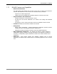
The front panel contains the antenna connections and mobile services connections, power and
local setup connections. The following figure shows the MA 850 front panel.
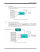
Figure 1-2. MobileAccess 850 Front View
Front Panel Ports
The following table describes the front panel ports.
Front Panel Ports Description
Antenna Ports Four n-type female antenna connections
Mobile Services
Four SMA female connections used in installations that integrate
MA 850 with MA 1000 RHUs or MA 2000 services.
NOTE: To be terminated with 50 ohm terminations when not in use.
Local RS232 connection for local setup (see section 4.1).
DC Power connection: 20V to 48V (see 2.3.3)
Front Panel LEDs
The front panel contains two LEDs, described in the following table.
Front Panel LEDs Description
Run Internal operation and channel operation status:
o Green blinking – unit OK
o Off – fault detected in unit
o Red blinking – failure of one of the channels
PWR (Unlabeled LED adjacent to the power connection).
Green – Power OK.
Mobile service connections
Antenna connections
Power
Local Setup