MobileAccess 850 (for FCC) Installation and Configuration Guide P/N: 709C001103 REV: A00 Date: 06-NOV-06
Preface Preface Material MobileAccess Ltd. Vienna, Virginia Tel: +1-703-848-0200 http://www.MobileAccess.
Preface Preface Material Preface Material © COPYRIGHT 2006, MOBILEACCESS NETWORKS INC. ALL RIGHTS RESERVED. MOBILEACCESSTM IS A REGISTERED TRADEMARK OF MOBILEACCESS. THIS DOCUMENT CONTAINS OTHER TRADEMARKS, TRADE NAMES AND SERVICE MARKS OF MOBILEACCESS AND OTHER ORGANIZATIONS, ALL OF WHICH ARE THE PROPERTY OF THEIR RESPECTIVE OWNERS.
Preface Preface Material Policy for Warrantee and Repair MOBILEACCESS TESTS AND INSPECTS ALL ITS PRODUCTS TO VERIFY THEIR QUALITY AND RELIABILITY. MOBILEACCESS USES EVERY REASONABLE PRECAUTION TO ENSURE THAT EACH UNIT MEETS THEIR DECLARED SPECIFICATIONS BEFORE SHIPMENT. CUSTOMERS SHOULD ADVISE THEIR INCOMING INSPECTION, ASSEMBLY, AND TEST PERSONNEL ABOUT THE PRECAUTIONS REQUIRED IN HANDLING AND TESTING OUR PRODUCTS. MANY OF THESE PRECAUTIONS CAN BE FOUND IN THIS MANUAL.
Preface Preface Material Reporting Defects THE UNITS WERE INSPECTED BEFORE SHIPMENT AND FOUND TO BE FREE OF MECHANICAL AND ELECTRICAL DEFECTS. EXAMINE THE UNITS FOR ANY DAMAGE THAT MAY HAVE BEEN CAUSED IN TRANSIT. IF DAMAGE IS DISCOVERED, FILE A CLAIM WITH THE FREIGHT CARRIER IMMEDIATELY. NOTIFY MOBILEACCESS AS SOON AS POSSIBLE.
Preface Preface Material Certification MobileAccess products have met the approvals of the following certifying organizations: ISO 9001:2000 (from March 15, 2004) FCC Certification For US: FCC 47 CFT part 15 for 802.11b/g Per section 15.204B. ID:OJFMA850 will only be supplied as complete system per section 15.204(b) of rules. FCC certification for MA 850 is valid for use only with the following elements: Antenna types: section 2.4.1 in this User Guide AP Types: section 2.
Preface Preface Material Professional Installation of Transmitter According to FCC 15.203, if an intentional radiator has a standard antenna connector, it must be professionally installed according to FCC 15.203 regulations: 1. The MA850 cannot be sold to the general public. Only professional installer, qualified ("licensed") by MobileAccess for this purpose is aloud to install the MA850. 2. The installation must be controlled and follow the requirement of "Installation Manual" (P/N:709C001103).
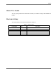
Preface Preface Material About This Guide This user guide provides all the information necessary to install and configure the MobileAccess MA 850. Revision History The revision history for this document is shown in Table 1-1.
Preface Preface Material List of Acronyms AGC Automatic Gain Control BDA Bi-Directional Amplifier BU Base Unit DL Downlink RHU Remote Hub Unit SNR Signal to Noise Ratio UL Uplink VDC Volts Direct Current AP Access Point MA 850 Installation and Configuration Guide IX
Preface Preface Material Table of Contents Preface Material .......................................................................................................................III Policy for Warrantee and Repair......................................................................................................... IV Certification ......................................................................................................................................
Preface Preface Material 2.3.4 Power Connections ...........................................................................................................11 2.4 In-building Antennas ..................................................................................................................12 2.4.1 Antenna Types .................................................................................................................12 2.4.2 Antenna Connections ................................................
Preface Preface Material Specifications.........................................................................................................................
1 Introduction to the MA 850 System This chapter provides a description of the MA 850 system, its architecture, installation configurations, operation and required commissioning procedures. 1.1 About MobileAccess MA 850 Figure 1-1. MobileAccess 850 The MA-850 Wi-Fi Module enables 802.11b/g Wi-Fi signals to be combined with other wireless services for simultaneous distribution over the MobileAccess Universal Wireless Network.
About MobileAccess MA 850 1.1.1 MA 850 Features and Capabilities • Multi-use infrastructure: The same cables and antennas used for Wi-Fi can be used to support the simultaneous extension and distribution of other wireless voice and data services, as follows: • o Support for four 802.
MA 850 Front and Rear Panels 1.2 MA 850 Front and Rear Panels This section describes the MA 850 front- and rear-panel connections and LEDs. 1.2.1 Front Panel Connections and LEDs The front panel contains the antenna connections and mobile services connections, power and local setup connections. The following figure shows the MA 850 front panel. Local Setup Power Antenna connections Mobile service connections Figure 1-2.
MA 850 Front and Rear Panels 1.2.2 Rear Panel Port Connections and LEDs The rear panel contains the 802.11b/g AP connections, Ethernet connection for remote management and antenna sensing connector. Antenna sense connection 802.11b/g AP connections Ethernet port MAC Address Figure 1-3. MobileAccess 850 Rear View Rear Panel Ports The following table describes the rear panel ports. Rear Panel Ports Description 802.11b/g APs Four 802.11b/g connections. (See LED descriptions in the following table).
Unit Architecture 1.3 Unit Architecture MA 850 consists of the following main functional modules: • Interface: Provides interface to the 802.11b/g AP ports. • Gain control mechanism: Gain control to adjust 802.11b/g signals to specific site • Combining and separating mechanism: On the downlink, combines the amplified 802.11b/g signals with the 802.11a AP signals and those of mobile services. On the uplink, separates the signals and routes them to the corresponding ports.
Installation Configurations 1.4.1 Standalone In this type of installation configuration, MA 850 distributes only 802.11b/g services over the connected antenna infrastructure. Figure 1-5. MA 850 Standalone Installation Configuration 1.4.2 Add-On to MA 1000 RHU The MA 850 can be installed as an add-on unit to a MA 1000 RHU.
Installation Configurations 1.4.3 Add-on to MA 2000 System The MA 850 can be installed as an (external) add-on unit to the MA 2000 system. In this type of installation, the combined MA 2000 services are routed to the MA 850 inputs where they are integrated with the MA 850 Wi-Fi data services and, through the MA 850 antenna connections, distributed through the same coax broadband antenna infrastructure. Figure 1-7.
Signal Distribution in the MA 850 1.5 Signal Distribution in the MA 850 The MA 850 distributes the 802.11b/g signals from each AP port to the corresponding antenna port. For example, the signals from an AP connected to MA 850 b/g-1 are routed to antenna1; signals from an AP connected to MA 850 b/g-2 are routed to antenna-2, etc.
2 Infrastructure Preparation This chapter contains information on the cabling and power requirements for the MA 850 system, as well as the antenna types and access points that can be used. 2.1 Installation Requirements The infrastructure preparation consists of two main phases: 1. Floor Planning: Planning the distribution of the antennas on each floor to provide the required coverage.
Coaxial Cable Connections 2.2 Coaxial Cable Connections 2.2.1 General Cable Installation Procedures • Observe the general cable installation procedures in accordance with the building codes in your area. • The building code requires that all cabling be installed above ceiling level (where applicable). Each length of cable from the risers to each antenna must be concealed above ceiling. • The cable must be properly supported and maintained straight.
Power Consumption, Connections and Power Supplies 2.3 Power Consumption, Connections and Power Supplies 2.3.1 Power Safety Instructions SAFETY WARNINGS When installing or selecting the power supplies: 1. Be sure to disconnect all power sources before servicing. 2. Calculate the required power according to the requirements of the specific installation and then determine the configuration of the power supplies. The required DC cables will then be determined by the selected PS configuration. 3.
In-building Antennas 2.4 In-building Antennas The in-building antennas are connected to the coaxial cable distribution system by jumper cables at various points. The antennas will be mounted on the ceiling tiles and should be exposed. All in-building antenna installations will be such that it will not interfere with indoor traffic and will not enable any person to touch the antennas. 2.4.1 • Wideband antennas omni – up to 2.5GHz to support 802.11b/g. Use any of the antennas listed in section 2.4.
Access Points 2.5 Access Points NOTE: If the MobileAccess 850 is operated without cellular service, it is required to connect 50Ω Ω termination points to each of the remote connectors in the unit. A 50 Ω termination is also required on each unused AP port. The following vendor Access Points have been verified and FCC approved. Table 2-4.
3 Installation This chapter contains the installation and connection procedures for various installation configurations. MA 850 may be installed in the following configurations: 3.1 • Wall mount standalone – mounted directly on the wall with four screws • Mounted onto an MA 1000 RHU • Mount as add-on to an MA 1000 RHU with an MA 1200 add-on unit • Add-on to a MA 2000 system Accessory Kits Verify that the supplied accessory kit corresponds to your installation.
Placing the Unit and Recording Location 3.2 Placing the Unit and Recording Location MobileAccess 850 is typically installed in the communication shaft or cabinet of each floor to which WLAN coverage is to be supported. The accessories, mounting and installation procedures vary depending on the installation configuration. NOTE: It is recommended to record the location of the units according to the MAC addresses on the sticker at the rear of the units near the Ethernet port. 3.
Add-on to an MA 1000 System Installation 6. Connect the network connection to the MA 850 rear panel network port. NOTE 1: Each unit is pre-assigned an IP address. The address can be modified anytime through a remote connection according to the procedure described in section 4.2.1). NOTE 2: It is recommended to record the location of the units according to the MAC addresses on the sticker at the rear of the units near the Ethernet port. 3.
Add-on to an MA 1000 System Installation NOTE: For antenna sensing support in RHU 1000 version 3.0 and lower, upgrade to a higher version according to the MA 850 Upgrade Procedure Guide. MA 1000 RHU MA 850 705102101 connector MAC Ethernet Address connection 802.11b/g/ AP connections 5. Connect the 802.11b/g Access Points to the corresponding ports on the MA 850 rear panel. Refer to section 1.5 for a description of the connections and distribution patterns.
Add-on to an MA 1000 System Installation 8. Connect the power. It is recommended to use the following power supply for local power configuration, where power can also be supplied using remote power supply configurations: • Dedicated power supply (i.e. LPS-48-100W which feeds both modules). Refer to the Power Supplies Manual. 9.
Add-on to an MA 1000 with MA 1200 3.5 Add-on to an MA 1000 with MA 1200 In this type of installation, the MA 850 and MA 1000/1200 assembly are separated by a bracket. NOTE: It is recommended to mount the MA 850 to the wall, and the MA 10001200 assembly on top of the MA 850 (with a bracket between them). However, if a previous MA 1000/1200 assembly exists, you may install the MA850 on top of the existing assembly, (with a bracket between them.) To assemble an RHU 1000 onto an MA 850 1.
Add-on to an MA 1000 with MA 1200 2. Mount the MA 850 and bracket assembly to the wall. When mounting, consider the following: • The type of screws used to mount the unit must suit the type of wall construction (cement, bricks, etc.) so that the mount is secure. • The position of the APs and required cable connections. 3. Assemble the MA 1000/1200 assembly to the 850 bracket. 4. For antenna sensing support (RHU 1000 version 3.
Add-on to an MA 1000 with MA 1200 7. Connect the MA 1000 antenna ports and the MA 850 Mobile Services ports using the four SMA to N-type cables supplied in the accessory kit. NOTE: Be sure the connectors are closed at a 45 degree angle so as not to place stress on the cables. MA 1200 MA 1000 MA 850 N-type SMA jumpers (included) Antennas Figure 3-3. Connection of MA 850 and MA 1000 Service Ports 8. Connect the power.
Add-on to an MA 2000 System 3.6 Add-on to an MA 2000 System MA 850 may be integrated into the MA 2000 system using one of the following installations: • Installing it directly on the MA 2000 RC top panel (using the supplied plate); • Mounting it on a rack (using the supplied plate); • Wall-mount near the MA 2000 cabinet. NOTE: The coax outputs of the cabinet are connected to the appropriate ports on the MA 850 and the antennas are connected directly to the MA 850 module. 3.6.
Add-on to an MA 2000 System Connection to Remote Cabinet antenna ports Figure 3-5. Illustration of MA 850 Mounted on MA 2000 RC 4. Connect the RC antenna ports to the MA 850 front panel port connectors as illustrated below. Figure 3-6. Illustration of RC Antenna port connections 5. Connect the antennas to the MA 850 antenna ports.
Add-on to an MA 2000 System 3.6.2 MA 850 Rack Mount 1. Assemble the side brackets as illustrated in Figure 3-4. 2. Assemble the MA 850 module to the supplied bracket using the four screws and washers. 3. Mount the assembly in the rack using the side brackets. Figure 3-7. MA 850 to Bracket Installation 4. Connect the RC antenna ports to the SMA connectors on the MA 850 front panel. 5. Connect the antenna to the MA 850 antenna ports. 3.6.
4 Configuration and Management It is required to perform the following configuration procedures: • Change the default IP address • Configure the unconnected antenna ports (if not all antennas are connected) The configuration is performed through a remote connection using a standard Web browser application (i.e. Explorer). After configuring the unit, each channel and the corresponding element may be monitored. NOTE 1: The unit may be configured either before or after the installation.
Local Configuration and Monitoring 4.1 Local Configuration and Monitoring This procedure is performed through the MA 850 Customer Tool application installed and launched from a computer that is locally connected to the MA 850 unit. For professional installer only This procedure is performed through the MA 850 Customer Tool application installed and launched from a computer that is locally connected to the MA 850 unit. 4.1.1 Getting Started 1.
Local Configuration and Monitoring 4.1.2 MA 850 Customer Tool Window Description The MA 850 Customer Tool window is displayed according to the instructions in the previous section. The window provides the channel configuration and monitoring options. It is divided into the following areas: • General information – versions, etc.
Local Configuration and Monitoring 4.1.3 Configuration Using MA 850 Customer Tool 1. It is assumed that you are now locally connected to the MA 850 and have launched the Customer Tool on you computer according to the instructions in the previous sections. 2. All antennas are configured by default as being connected (Antenna Select – Enable). For channels where an antenna is not connected, under Antenna Select, choose Disable.
Remote - Web Browser Session • • 4.2 Channel status – under Amp 1 to Amp 4 for the corresponding channel: • OK – channel OK • Fail – channel failure AP Status: • OK – AP detected • Fail – AP not detected at the port. Remote - Web Browser Session NOTE: Be sure that there is not an open local session (section 4.1) to the MA 850 unit before you attempt to open a remote session to the same unit; otherwise, the unit may stop responding.
Remote - Web Browser Session 4.2.1 IP Configuration Procedure MA 850 units connected to the network may be assigned either dynamic IP Addresses through DHCP or static IP addresses (for networks without DHCP). The addresses may be assigned from a single location using the Lantronix DeviceInstall application supplied with the units. The IP configuration procedure consists of the following steps: 4.2.1.1 • Installing and launching the Lantronix DeviceInstaller application on your computer.
Remote - Web Browser Session • Hardware Address – MAC address • Additional identification parameters that may be available 3. For networks with DHCP: • The dynamically assigned IP Address will also be listed in the IP Address column. 4. For networks without DHCP: • Disregard the data displayed in the IP Address column and assign a Static IP address according to Assigning a Static IP Address, page 31. What next ? Define the SNMP parameters according to Configuring the SNMP Parameters, page 34. 4.2.
Remote - Web Browser Session Figure 4-6. MAC Address 2. Click Next. The IP Address Assignment Method window appears. Figure 4-7. Static IP Address 3. Select Assign a specific IP address; then, click Next. The IP Settings window appears.
Remote - Web Browser Session Figure 4-8. Static IP Address Definition 4. Enter the IP Address, Subnet Mask and Default Gateway values; then, click Next. The Assignment window appears. Figure 4-9. Assignment Window 5. Click Assign to assign the MA 850 unit the defined parameters. Once the parameters have been assigned, the message ‘Completed Successfully’ appears and the Finish button is enabled.
Remote - Web Browser Session Figure 4-10. Finish Static IP Address Definition 6. Click Finish. The Device Installer Main window reappears and the installed unit will be listed in the window. What next? Define the SNMP parameters according to Configuring the SNMP Parameters, page 34. 4.2.1.4 Configuring the SNMP Parameters Configure the SNMP Community and Trap destination addresses according to the instructions in this section.
Remote - Web Browser Session 2. Click OK and immediately press Enter to go into Setup Mode. The current settings will be displayed, followed by the Change Setup menu. Change Setup: 0 Server configuration 1 Channel 1 configuration 3 SNMP configuration 7 factory defaults (for manufacturer use only DO NOT SELECT!!) 8 exit without save 9 save and exit Your choice ? 3. Enter 3 (SNMP Configuration). 4.
Remote - Web Browser Session 4.2.1.5 Configuring Serial Parameters This section describes how to verify and configure the serial communication parameters for each MA 850 unit. 1. From the DeviceInstaller Main window, select the MA 850 unit to be configured and click the Configure button the toolbar. The Configure Device dialog appears. Figure 4-12. Current Serial Port Parameters 2. Click the Ports tab and then the Edit Settings… button. The Port Properties dialog appears. Figure 4-13.
Remote - Web Browser Session 4.2.2 Login and User Levels You may login to the MA 850 unit through any Web browser. Two user levels are available: • guest (guestpass) – monitoring options only • admin (adminpass) – monitoring and configuration options NOTE: The password is case sensitive – use lower case letters. To login to the MA 850 configuration application 1. Run a Web Browser application (i.e. Internet Explorer). 2. Enter the IP Address of the MA 850 unit. (i.e. http://192.168.10.127).
Remote - Web Browser Session 4.2.3 MA 850 View Upon login, the MA 850 View shows the current 802.11b/gs AP and antenna connections. Menu options on the left side provide access to various configuration options as described in Table 4-1. Element color indications is described in Table 4-2. NOTE: The display is refreshed automatically; however, if necessary, be sure to use the application Refresh button in the menu options (and not the Web Browser refresh).
Gain Setting Table 4-2. MA 850 View Color Indications Option Description Green OK Red Error indication: Red AP – an AP is not connected or faulty. Red antenna – antenna not detected by antenna sense mechanism Red Amp – channel malfunction identified in the MA 850 unit Purple Location (not status) of backup AP in one-AP or two-AP configurations with in which the redundancy option is enabled.
Monitoring Alarms 2. For the relevant channel, change the gain. Range = -10 to +5 dB 3. Click Accept. The gain value for the channels at the unit is displayed under the Gain Value column. 4.4 Monitoring Alarms MA 850 provides the following alarms, which may be viewed by clicking the Alarms button in the Main window: • Access Point Sense – senses the connection of configured APs • Low power – internal channel operation status • Antenna sense – senses connected antennas.
Traps List 5 SNMP Management Using Any Standard SNMP Manager The MA 850 packages provide MIBSs that enable standard SNMP (Version 2.0) managers such as HP OpenView to view event traps sent by the MA 850 unit and to configure the unit. One MIB file is provided: MA-XPORT850-MIB– describes the architecture of the managed elements and contains the events in the system NOTE: These traps provide a general indication of the type of failure.
Traps List To view the traps using any standard SNMP manager NOTE: It is assumed that the IP Address of at least one destination is already defined. From a computer configured as a trap destination (configured to receive the traps), load the two MIB files to the SNMP manager. The following figure shows the MIB tree that includes the loaded MobileAccess 850 file. Figure 5-1.
Specifications 802.11b/g RF Parameters Bandwidth Gain TX Gain RX NF RX Flatness 2400 - 2485 MHz 0 dB per port 10 dB 7 dB ±1.5 dB Mobile Services/WMTS Parameters MA-850 MA-850U Mobile Services Cell PCS WMTS Band (MHz) 608-960 13951990 Insertion Loss (dB/port) 1.0 Flatness (dB) +/- 0.5 WMTS Cell DCS WMTS UMTS 608-960 13951880 19202170 2.0 1.0 2.0 3.0 +/- 1.0 +/- 0.5 +/- 1.0 +/- 1.5 WMTS RF Connections 802.
Traps List Environmental Specifications Temperature Operating Storage 0°C to +50°C (32°F to 122°F) -20°C to 85°C (-4°C to 185°C) Humidity Operating Storage 95% (non-condensing) 95% (non-condensing) Standards and Approvals USA FCC–47 CFR 15 UL 60950-1 CAN/CSA C22.