
User's Manual


Appendix I: Optical test Procedures
Optical Back-reflection Testing
MA 2000 Installation and Configuration Guide 73
7.3 Optical Back-reflection Testing
This section describes the optical back-reflection testing of SM SC/APC connectors at each
end of an optical cable.
7.3.1 Required Test Equipment
1. Adjustable1310 nm Stabilized Laser Source with output power greater than 7dBm
2. 1310 nm Optical Power Meter with a measurement range of up to -70 dBm
3. One low loss Singlemode 1310 nm 2x2 50%/50% Fiber Optic Coupler with SC/APC
connectors at all four fiber pigtailed ports. Pigtail length should be 50 cm.
4. One SC/APC Adapter
7.3.2 Test Procedure
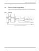
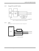
1. Refer to the following figure for port definitions of the Fiber Optic Coupler. The coupler is
symmetrical but for our purposes, each port should be identified as shown in Figure 1-4.
Figure 7-4. Port Identification
2. Measure the loss from port I1 to O1 according to the insertion loss method described in the
previous section. This loss will be referred to as LI1O1. It should be approximately 3.5 dB.
3. Measure the loss from port O1 to I2 in a similar manner. This loss will be referred to as
LO1I2. It should also be approximately 3.5 dB.
4. Calculate Total Loss, TL where TL= LI1O1 + LO1I2. TL should approximately 7dB.
5. Adjust the laser output power in dBm to the same value as TL.
For example, if TL = 7dB, adjust the laser output to 7 dBm.