
User's Manual


System Installation
Communication Room Installation
MA 2000 Installation and Configuration Guide 44
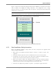
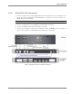
4.2.3.2 Connections to Additional BUs
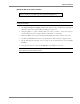
To connect more than four 8-port BUs or more than eight 4-port BUs to the RIU:
• Connect an 8W splitter to the Downlink connector on the RIU front panel.
• Connect an 8W combiner to the Uplink connector on the RIU front panel.
• Connect additional BUs to the uplink and downlink connections.
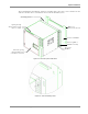
Expansion ports
BTSCBTSC
BTSCBTSC
BTSCBTSC
Combiners
/Splitters
Compartment*
UL and DL
connections to
four BU8 modules
UL and DL connections
to up to four additional
BU8 modules
External 1:8 splitter
/combiner
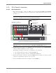
4.2.4 BU Connections
NOTE: It is assumed that the patch panel cabinet (SC/APC adaptors) for fiber optic cable connections is
installed in the rack near the BUs.
1. Connect fiber jumper between splice tray and patch panel cabinet.
2. Connect fiber jumpers between the corresponding BU optical ports and the patch panel.
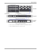
Figure 4-3. BU Front Panel Connections
3. Connect the BU rear panel Uplink and Downlink ports to the corresponding ports on the
RIU rear panel.
The following figure shows the BU connections to an RIU Chassis and MA 410/430 controller.