
User's Manual


System Installation
Communication Room Installation
MA 2000 Installation and Configuration Guide 42
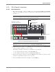
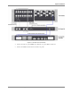
Figure 4-1 shows the recommended physical location of the MobileAccess elements in the rack in
order to facilitate and simplify the cabling
connections.
The configuration is for a single
operator. If the site is serviced by more than one operator, each operator often installs their
equipment in a separate rack.
NOTE: Note that the MobileAccess 430 controller is at eye level to provide an easy view of the LED
indicators and LCD display and easy access to the local and remote monitoring connections.
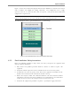
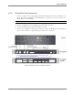
The following figure shows a typical installation for a two field design.
Figure 4-1: Recommended Order in the Communication Room Rack
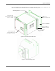
4.2.2 Rack Installation Safety Instructions
Review the following guidelines to help ensure your safety and protect the equipment from
damage during the installation.
• Only trained and qualified personnel should be allowed to install or replace this
equipment.
• Verify that ambient temperature of the environment does not exceed 50°C (122°F)
• To maintain a low center of gravity, ensure that heavier equipment is installed near the
bottom of the rack and load the rack from the bottom to the top.
• Ensure that adequate airflow and ventilation within the rack and around the installed
components so that the safety of the equipment is not compromised. It is recommended
to allow for at least about 2 cm of airspace between devices in the rack.
• Verify that the equipment is grounded as required – especially the supply connections.