
User's Manual


System Installation
Communication Room Installation
MA 2000 Installation and Configuration Guide 41
4.1.1 Unpacking and Inspection
This section provides instructions for opening the shipping boxes, verifying that all parts have
been received, and verifying that no shipping damage has occurred.
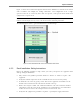
Unpack and inspect the cartons according to the following procedure
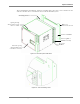
1. Open the shipping carton and carefully unpack each unit from the protective packing
material.
2. Check for signs of external damage. If there is any damage, call your MobileAccess service
representative.
4.2 Communication Room Installation
The Communication Room installation consists of the following basic steps:
1. Unpacking and inspecting the MA 2000 units (see 4.1.1)
2. Mounting the RIUs, BUs and 410/430 controllers in the mounting rack (see
4.2)
3 RF connections BTS/BDA connections.
4. RF connections to the Base Units.
5. Connecting the MA 410/430 control connections to the units
6. Connecting DC power to the units
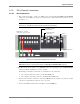
4.2.1 Rack Installation General Instructions
NOTE: Usually, each operator installs the equipment that supports their services in a separate rack.
It is recommended to install the following MobileAccess system modules in a 19” rack in the
communication room
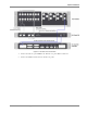
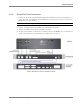
• RIU Chassis 3U, RIU Lite 2U
• BU 1U
• MobileAccess 410/430 controller 1U
• Fiber Optic patch panel and splice tray
• Power supply/supplies (MobileAccess – 3U for each unit; units from other manufacturers
may vary in size)
Verify that the rack height can support all the units to be installed, where you may also want to
consider future expansions.