
User's Manual


MA 2000 System Elements
MA 2000 Remote Management Elements
MA 2000 Installation and Configuration Guide 27
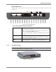
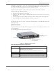
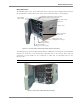
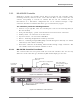
The rear panel of the unit contains four low-band and four high-band ports as well as the control
port.
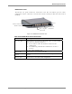
Figure 2-21. 8x4 Combiner Rear Panel
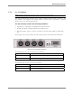
The following table describes the rear panel connectors.
NOTE: Connector on rear panel is for future option.
SMA Connectors Description
Low Band Four connectors for the low-band outputs of the corresponding
remote unit. Refer to
Chapter
6
for the exact connections
relevant to each configuration.
High Band Four connectors for the high-band outputs of the
corresponding remote unit. Refer to
Chapter
6
for the exact
connections relevant to each configuration.
Control Interfaces to the Digital card (that enables antenna monitoring)
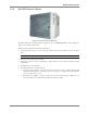
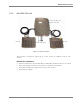
2.3 MA 2000 Remote Management Elements
NOTE: This section provides general information on the MobileAccess NMS. For detailed information on
the controller, configuration and connections refer to the Mobile Access NMS User
’
s Guide.
The system elements can then be monitored via a connection to the host controller. The type of
connection and monitoring depends on the type of controllers that are installed, the
configuration and the available management applications:
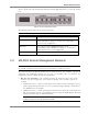
• MA 410/430 Controller – The controller provides the interface between the system
elements and the management and control mechanism. Two controller models are
available:
• MobileAccess 410™ – enables management of the connected devices through a local or
point-to-point dial-up connection. It can be remotely managed through a connection to
the MobileAccess 430 controller.
• MobileAccess 430™ – enables management of all connected elements and all connected
MA 410 controllers and the corresponding elements. Supports SNMP (Simple Network
Management Protocol) over TCP/IP connection.
NOTE: MA 430 may be managed through the Network Operator Center (NOC) through Manager
of Mangers element such as HP OpenView via SNMP.