
User's Manual
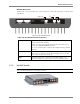


MA 2000 System Elements
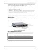
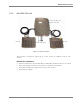
MA Remote Location Elements
MA 2000 Installation and Configuration Guide 24
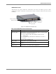
Open door views
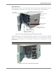
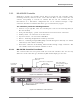
The following figure shows an open RC 2000 cabinet, integrated power supply model, with four
RU 2000 modules and four filters. (For clarity, the internal connections are not included).
Figure
2-17. RC 2000 Open Cabinet View (without internal connections)
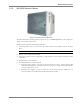
The following image shows the MA 2000 RC with the cabling. The antenna ports of the individual
modules are connected to the internal RF connections and to the relevant filters. The PS
connections of each module are also connected to cables that are internally routed to the
integrated PS.
NOTE: The fiber optic connections are not displayed.
Figure 2-18. RC Open Cabinet with Internal Cabling
Optic fiber connection from
the corresponding BU
Slot for fitting
Optic Fibers
AC power input to
integrated power supply
Internal DC module
connections
Splitter/Combiner
connections
Filters (four in this
configuration example)
Connection to
external battery
Antenna ports