
User's Manual


System Installation
Communication Room Installation
MA 2000 Installation and Configuration Guide 43
4.2.3 RIU (Chassis) Connections
4.2.3.1 RIU Connections
1. RIU to BU connections: connect each BU to the corresponding RF Uplink and Downlink
connectors on the RIU
rear panel
. For connections to more than four 8-port BUs, refer to
section
4.2.3.2.
NOTE: Each pair of uplink and one downlink RIU rear-panel ports are used to connect one OPTM. See
section 2.1.2. Two pairs are used to connect an 8-port BU (two OPTMs)
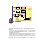
Figure
4-2. RIU Rear Panel showing the RF Connection
NOTE: Up to four 8-port BU may be connected. Additional BUs may be connected through the
Extension connector on the front panel. Refer to Connecting to Additional BUs, page 44.
2. BTS/BDA connections: Connect each BTS/BDA to the corresponding rear panel BTSC/BDAC)
connectors (BTSC and BDAC are service specific).
Both simplex and duplex connections are available for each connection:
• For a duplex connection, connect to the BTSC DUP port;
• For a simplex connection, connect to the BTSC UL and DL ports;
3. MA 410/430 controller connection: connect the RS485 port on the RIU rear panel to the MA
410/430 rear panel RS232 connector: port-1 or port-5.
4. Connect the Power connections to the RIU rear panel PWR port.
MobileAccess 1000 BU
connections (pair per BU)
Power
Controller connection
BTS/BDA duplex
connections
BTS/BDA simplex
connections