
Installation Guide


Litenna
Installation Guide Optical Test Procedure
Foxcom Wireless Proprietary Information Document No.
42-93-005-23D
41
Measuring Return Power
1. Move light source from connector #3 to connector #1.
2. Connect cable being tested to output connector #3.
3. If coupler has two outputs, then make a pigtail at second output.
4. If cable is longer than 100 meter, then cable needs to be isolated.
To isolate cable:
a) Find place near test point where winding the cable into a pigtail is possible.
b) Make pigtail.
5. If cable is shorter than 100 meter, then verify that cable is disconnected at end.
6. Measure the return light power (P2), connector #2.
Calculating Return Loss
Calculate the difference between the signals in dB.
(Return loss)dB = (P2)dBm – (P3)dBm + (Lc)dB
Results
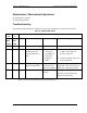
The following table is filled in by technical personnel testing the fiberoptic cables.
Table 7 - Fiberoptic Cable Test Results
Test Measurement Pass Range Pass/Fail
Optical Insertion loss <0.5 dB/Km
Optical return loss < -50 dB
Summary
If the fiber fails in the optical insertion loss or optical return loss tests, then the
connector needs to be cleaned. Connector cleaning is carried out according to a
standard cleaning procedure. Following cleaning, the fiber needs to be tested again. If
the failure continues in the fiber following cleaning, then the technical personnel need to
refer to the fiberoptic cable manufacturer’s troubleshooting guide.
If the fiber passes the optical insertion loss and optical return loss tests, then the tested
fiberoptic cable is considered suitable for use with Foxcom Wireless equipment.