
Installation Guide


Optical Test Procedure Litenna
Installation Guide
40 Document No.
42-93-005-23D
Foxcom Wireless Proprietary Information
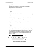
Optical Return Loss Measurement Test
Connection description: Connect a light source and optical power to the inputs. If the
coupler has one output, connect the tested cable to this output. If the coupler has two
outputs make a pigtail at the second output.
Light
source
Optical
power
meter
IN OUT
(pigtail)
Cable Being Tested
2
1
3
4
"Optical Terminator"
Optical Coupler
Figure 20 – Optical Return Loss Measurement
Measurement Procedure
Measuring Power Input To Cable Being Tested
1. Verify that light source power is at 0dBm.
2. Connect a light source to connector #1.
3. Connect optical power meter to connector #3.
4. Measure signal power (P3), power should be approximately –4dBm.
Measuring Coupler Power Loss
1. Move power meter from connector #3 to connector #2.
2. Move light source from connector #1 to connector #3.
3. Measure power loss of coupler (Lc).