
Installation Guide


Litenna
Installation Guide Optical Test Procedure
Foxcom Wireless Proprietary Information Document No.
42-93-005-23D
39
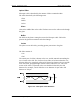
Method #2: Single Point Test
Connection description: This method assumes that there are two parallel fibers on
the path to be tested. Connect fiber jumper at end of the cable being tested to
another parallel cable. Connect the light source, optical power meter and optical
jumper as shown in Figure 19.
This measurement can test two cables simultaneously.
Light
source
Optical
power
meter
Connector
Fiber optic jumper
Figure 19 – Single Point Test
1. Use optic jumper to connect the two cables.
2. Connect light source directly to the optical power meter.
3. Measure the power of light source signal , verify power of 0dBm.
4. Connect a light source and optical power meter to one end of each cable.
5. Measure the power of the signal.
6. Calculate the difference between the two signals in dB
Other Test Equipment
The optical insertion loss measurement test can be performed with more
sophisticated measurement equipment.
For information on other types of test equipment contact Foxcom Wireless.
(Insertion loss)dB =(Light source signal)dBm– (Measure signal)dBm