
Installation Guide


Litenna
Installation Guide Power Supply for Litenna
Foxcom Wireless Proprietary Information Document No. 42-93-005-23D 31
The power supply that drives the Litenna™ system can be purchased from Foxcom Wireless.
Four power supply options are available.
Option One
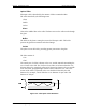
In this option the BU is connected to the power supply via electrical cables. In order to
power the RHU from the Power supply, two copper electrical wires running through the
building (separately from the fiberoptic cables) supply power to each RHU in parallel.
For this configuration, electrical power calculations need to be made. This option is
shown in Figure 15.
Option Two
This power supply is located near the BU. The Power supply will drive the BU and
RHUs. To provide power, the BU is connected to the power supply via electrical cables.
To supply power to the RHU, a composite cable is used (composite cable contains two
fiber cables and two copper electrical wires in the same jacket). For this configuration,
electrical power calculations need to be made. See example in Figure 14.
Option Three
In this option the power supply type is a stand alone configuration. Power for both the
BU and RHUs will be supplied separately. In this configuration each unit will be co-
located with a power supply. This will not require long electrical cable runs.
Table 6 - Power Supply Options
Materials
Model
Stand alone 15W LPS-15-48
Stand alone 100W LPS-100-48
Rackmount 100W LPS2-100-48
Rackmount 300W LPS2-300-48