
Installation Guide


Installation Litenna
Installation Guide
20 Document No. 42-93-005-23D Foxcom Wireless Proprietary Information
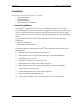
Installation
The following sections describe the Litenna
TM
installation.
•
General Installation.
•
Fiber Installation.
•
Hi Rise Installation.
•
Horizontal Layout Installation.
General Installation
The Litenna
TM
components need to be set up, followed by performance verification
before installing the system. Foxcom Wireless suggests that a 19” rack-mountable Splice
Tray be used at the Base Unit to facilitate optical fiber splicing. In the rack, the Splice
Tray is mounted above or below the Base Unit (depending on direction of the incoming
cables).
Set up procedures for the Litenna
TM
Base and Remote units are for the following
installations:
•
High rise installation.
•
Horizontal Layout installation.
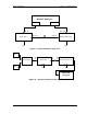
For both installations, setting up the Litenna
TM
Base and Remote units consists of the
following steps:
1. Determine antenna placement by system engineer.
2. Pull composite cable or separate fiber and copper cables through building.
3. Install Base Unit in 19” rack.
4. Install Splice Tray for Base Unit in 19” rack.
5. Install patch panel cabinet with SC/APC connectors.
6. Fiber contractor splices fiber cable with SC/APC to connectorized pigtails.
7. Connect Microcell to Base Unit.
8. Connect Remote Hub Unit to base unit through fiber.
9. Connect Antennas to Remote Hub Unit.
10. Connect power supply to base unit and remote refer to power planning.