
Installation Guide


Litenna
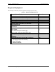
Installation Guide Required Equipment
Foxcom Wireless Proprietary Information Document No. 42-93-005-23D 19
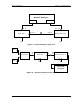
Uplink Network Test
To carry out the Noise Floor test, the following procedure needs to be carried out.
1. Connect the Spectrum Analyzer to the Base Unit uplink port.
Connect 50ohm terminators to the RHU ports, and to all Base Unit uplink
ports except for the tested port (see Figure 11).
2. Extra amplification (25db) is applied between Base Unit and Spectrum
Analyzer in order to measure the noise floor.
3. Set Spectrum Analyzer to:
Video BW 300hz
RBW 1khz
Attenuation 0db
Span 0hz
Center freq. Refer to
Product Spec.
Ref level -50dbm
Marker noise ON
4. The noise figure is formulated as: -174 + Gsystem + noise floor
(On the RHU, all unused ports must be terminated with 50ohm load.)
Remote Hub Unit
Base Unit
Spectrum
Analyzer
18V
18V
RF
In
Opt
Out
Opt
In
RF
Out
DC
In
DC
In
Uplink
1
8
.
.
AMP
.
.
Figure 11 – Uplink Network Test