
Installation Guide


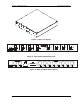


Required Equipment Litenna
Installation Guide
16 Document No. 42-93-005-23D Foxcom Wireless Proprietary Information
Test Procedures
This section explains the following test procedures:
•
Pre RF Test
•
Flatness Test
•
Gain/IP3 Test
•
Uplink Network Test
In order to carry out the tests, the following connections need to be made.
1. Connect the Base Unit optical output to the RHU optical input via fiberoptic cable.
2. Connect power to all units being tested (18V-48V DC).
Use the relevant setup for every test.
Pre RF Test
To carry out the Pre RF Test, the following procedure needs to be carried out.
1. Make sure all DC LEDs are lit on both units.
2. Measure Tx optical output power for all lasers.
Output power should be 1.5-2.4mW (with optical power meter).
3. On the RHU, Make sure that the optical LED is lit.
4. On the BU, make sure the Rx optical LEDs are lit.
Flatness Test
To carry out the Flatness Test, the following procedure needs to be carried out.
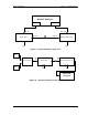
1. Connect the Network Analyzer to the designated Base Unit.
On the Network Analyzer, Base Unit connects to port 2.
On the Network Analyzer RHU connects to port 1 (see Figure 9).
2. After calibrating the network, set Network Analyzer to:
Measure S21
Format Log
Scale 1db/div
3. Apply with the required F1 and F2 should be according to Product Spec.
4. Measure the difference between the highest and the lowest signal point,
which should be as specified in the data sheet.