
Installation Guide


Introduction to Litenna Litenna
Installation Guide
12 Document No. 42-93-005-23D Foxcom Wireless Proprietary Information
Product Drawings
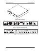
The following drawings show sample front and rear panels of the Litenna
™
units.
Figure 1 - Base Unit 4 ports
Figure 2 - Base Unit Front Panel 4 ports
Figure 3 - Base Unit Back Panels 4 ports
Pin # 1
Pin # 14
Pin # 13
Pin # 25
Coax Input from Cellular Headend (Microcell)
Coax Outputs to Cellular Headend (Microcell)
Optical Diode Input from RHU
Laser Output connection to RHU