
User's Manual

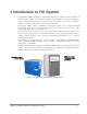
Table Of Contents
- Reporting Defects
- NOTE: Keep all packing material until you have completed the inspection
- Compliance with RF safety requirements:
- MobileAccess products have no inherent significant RF radiation.
- Compliance with RF safety requirements:
- ISO ISO 9001: 2000 and ISO 13485: 2003
- About this Guide and Other Relevant Documentation
- Table of Contents
- Introduction to HX System
- System Installation
- Rack Brackets (supplied screws)
- Commissioning MA Head-End
- Provisioning the MobileAccessHX
- Appendix A: System Specifications
- Appendix B: Ordering Information
- Appendix C: Site Preparation

MobileAccessHX Installation and Configuration Guide 1
1
1
I
I
n
n
t
t
r
r
o
o
d
d
u
u
c
c
t
t
i
i
o
o
n
n
t
t
o
o
H
H
X
X
S
S
y
y
s
s
t
t
e
e
m
m
The MobileAccessHX is a high power, Distributed Antenna System (DAS) solution for indoors or
outdoors (future option). It is a fiber-fed, compact, scalable multi-service platform designed to
provide complete RF open space coverage for large scale public venues, such as campuses,
stadiums, convention centers, hotels, airports, and train stations.
HX supports multiple wireless technologies and operator services over a single broadband
infrastructure. Using low loss fiber optic cabling remote units can cover distances of up to 2Km
from the BTS signal sources at the head-end.
Front-end wireless RF services are routed, over optic fibers, to HX series remote units that are
securely located at each remote location. These modular service aggregation platforms precisely
combine multiple wireless service signals for simultaneous distribution over a common
broadband infrastructure.
The solution can be deployed in new sites or alongside existing MobileAccess1000 (MA1000)
and/or MobileAccess2000 (MA2000) systems, sharing a common head-end and element
management system (EMS).
Alongside MA1000/MA2000 deployments, MobileAccessHX provides a comprehensive indoor and
outdoor coverage solution for varying site requirements, supporting everything from high-rise
buildings and campus topologies to stadiums and airports.
Figure 1-1. HX Indoor Model and HX Outdoor Model (FUTURE)
HX Remote Unit
– Outdoor Model
(FUTURE)
HX Remote Unit –
Indoor Model