
User's Manual
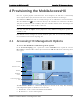
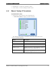
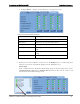
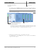
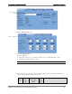
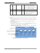
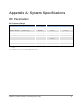
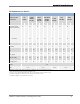
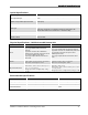
Table Of Contents
- Reporting Defects
- NOTE: Keep all packing material until you have completed the inspection
- Compliance with RF safety requirements:
- MobileAccess products have no inherent significant RF radiation.
- Compliance with RF safety requirements:
- ISO ISO 9001: 2000 and ISO 13485: 2003
- About this Guide and Other Relevant Documentation
- Table of Contents
- Introduction to HX System
- System Installation
- Rack Brackets (supplied screws)
- Commissioning MA Head-End
- Provisioning the MobileAccessHX
- Appendix A: System Specifications
- Appendix B: Ordering Information
- Appendix C: Site Preparation

Provisioning the MobileAccessHX Basic Setup Procedure
MobileAccessHX Installation and Configuration Guide 26
• Service Alarms – displays specific alarms for each supported service.
Table 4-2. HX Service Alarms Description
Alarm Description
Service Off Service disabled by the User
Adjustment Adjustment for target DL Output Power
VSWR Alarm Antenna disconnected (VSWR > 5:1)
DL Output Power High
DL Output Power > “Target Adjustment value” +
2dB
DL Output Power Low DL Output Power < “Target Adjustment value” 1
15dB
Over Temperature
Ambient temperature inside the HX unit >65°C
2. Mask irrelevant alarm conditions, in both tabs via the Modify button, to avoid having them
reflected overall status of the HX unit (displayed in the
HX Alarms
area).
For Example
In the example below, the
HX Cabinet Alarms
dialog shows the alarm response if the Service
2 DL Output Power Low alarm is NOT masked (enabled). In that case the
Service 2
and
Overall Status
will be RED indicating a fault.