
User's Manual
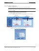
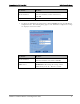
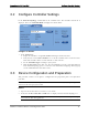
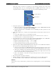
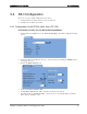
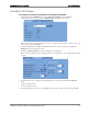
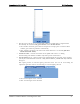
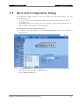
Table Of Contents
- Reporting Defects
- NOTE: Keep all packing material until you have completed the inspection
- Compliance with RF safety requirements:
- MobileAccess products have no inherent significant RF radiation.
- Compliance with RF safety requirements:
- ISO ISO 9001: 2000 and ISO 13485: 2003
- About this Guide and Other Relevant Documentation
- Table of Contents
- Introduction to HX System
- System Installation
- Rack Brackets (supplied screws)
- Commissioning MA Head-End
- Provisioning the MobileAccessHX
- Appendix A: System Specifications
- Appendix B: Ordering Information
- Appendix C: Site Preparation

Commissioning MA Head-End Device Configuration and Preparation
MobileAccessHX Installation and Configuration Guide 17
Verify that all the elements are displayed in the Network Topology pane under their
corresponding hosts, and are colored green, red, or yellow. Any of these colors are
acceptable before the adjustment procedure has been performed (following sections).
3. Verify that the BU is set to operate with RIU:
• Click on the BU item in the Network Topology Tree Select RF Parameters Tab
from the Work Area Interface Type to MA RIU
• Optional: Assign the BU an identifiable name by Modifying the Name parameter in the
Module Info tab
4. Using a Fiber Optic Tester, verify that the UL Optical Link Level of the fiber connected to the
BU is >0
• Set the Fiber Optic Tester to a wavelength of 1310nm
• Unplug the UL fiber connection from the BU and test to make sure it is at a level >0
• If the level is not >0, clean the fiber and retest
5. Set up CW signal to be connected to the signal conditioner (BTSC/BDAC). The 700 MHz LTE
conditioner does not need an external CW signal (See Section
3.3.3).
• BTSC acceptable input power range = +10 to +36dBm
• BDAC acceptable input power range = -16 to +10 dBm
• Acceptable frequency range depends upon the RF service
6. Adjust the signal conditioner (BTSC/BDAC) with the CW signal. The 700 MHz LTE conditioner
does not need an external CW signal. (See Section
3.3.3).
• Connect the CW signal to the BTSC/BDAC DL Port or Duplex port located on the rear of
the RIU associated with the slot that the signal conditioner (BTSC/BDAC) is inserted into
• Click on the conditioner in the Network Topology Tree Select RF Parameters Tab from
the Work Area Adjust Max Input Power by clicking on the Adjust button in the DL
Power section Select Use Current Input Power
• After a few moments, verify that the Target Max Input Power and the Current Input
Power are equivalent
7. Repeat Step 6 for each signal conditioner
8. Perform a Quality and Integrity Check of the installed system as per the RF Design and
Statement of Work. Contact a MobileAccess Project Manager for more instructions.
Phase II
These Phase II steps should only be performed after completing Phase I of the commissioning
process.
BTSC Modules
Controller Element
OPTM (BU) Modules