
User's Manual
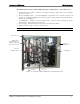
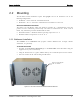
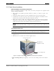
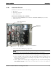
Table Of Contents
- Reporting Defects
- NOTE: Keep all packing material until you have completed the inspection
- Compliance with RF safety requirements:
- MobileAccess products have no inherent significant RF radiation.
- Compliance with RF safety requirements:
- ISO ISO 9001: 2000 and ISO 13485: 2003
- About this Guide and Other Relevant Documentation
- Table of Contents
- Introduction to HX System
- System Installation
- Rack Brackets (supplied screws)
- Commissioning MA Head-End
- Provisioning the MobileAccessHX
- Appendix A: System Specifications
- Appendix B: Ordering Information
- Appendix C: Site Preparation

System Installation Connections
MobileAccessHX Installation and Configuration Guide 10
2.3 Connections
The HX main connections consist of the following:
• RF antenna
• Fiber Optic connection
• Power connections
Connect the HX Indoor unit as follows
1. Connect broadband ANTENNA coax to HX cabinet DUPLEXED ANTENNA port (external).
2. OPEN cabinet door.
3. Connect F/O cables to RHU optic port (internal).
NOTE: Keep in mind the rules for handling and connecting F/O cables. The F/O cables will
be connected to the associated BU in the communication room at a later phase.
• Install splice box near Remote Cabinet.
• Connect fiber optic cable to splice box and the SC/APC pigtails to the HX RHU module.
• For the downlink, connect the fiber optic cable pigtails from splice box coming from the
BU port to the corresponding RU port (routing the optic fibers so they will fit through the
top opening in the door.)
• For the uplink, connect the fiber optic cable pigtails from splice box from the RU (routing
the optic fibers so they will fit through the top opening in the door), to the uplink port
that connects to the BU.
Duplexed RF
antenna port
Fiber optic port on HX
RHU module
AC power
Location of
DC power
Figure 2-3. HX connections