
User's Manual
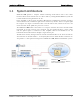
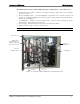
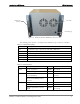
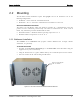
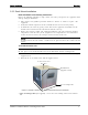
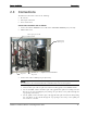
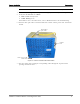
Table Of Contents
- Reporting Defects
- NOTE: Keep all packing material until you have completed the inspection
- Compliance with RF safety requirements:
- MobileAccess products have no inherent significant RF radiation.
- Compliance with RF safety requirements:
- ISO ISO 9001: 2000 and ISO 13485: 2003
- About this Guide and Other Relevant Documentation
- Table of Contents
- Introduction to HX System
- System Installation
- Rack Brackets (supplied screws)
- Commissioning MA Head-End
- Provisioning the MobileAccessHX
- Appendix A: System Specifications
- Appendix B: Ordering Information
- Appendix C: Site Preparation

Introduction to HX System HX Unit Interfaces
MobileAccessHX Installation and Configuration Guide 6
Figure
1-4. Example of Indoor HX Remote Unit rear View
The following tables provide a description of the HX indoor type connectors and LEDs.
Table 1-1. Connector Descriptions
Connector Description
F/O SC/APC fiber-optic connector for either SM or MM fibers
Antenna N-Type female 50Ω duplexed connector for RF antenna
AC PWR 110/220 VAC power feed
DC Direct 48VDC power feed
RS-232 Local craft connector
Grounding Grounding lug
Table 1-2. LED Descriptions
Name Description Color Status
Power Device is powered GREEN Steady On
Power not supplied to the unit GREEN Off
Comm When connected and discovered
by an OPTM (BU)
GREEN Blink per communication
attempt
When device is powered on but
no external communication is
received
GREEN Steady Slow Blink
Link No Optical link is present GREEN Off
Low optical link level from OPTM GREEN Blink
Normal optical link level from
OPTM
GREEN
Steady On
Grounding lug
Fans holes
Wall mount
brackets