
User's Manual
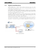
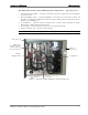
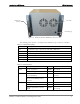
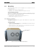
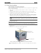
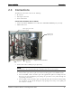
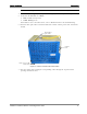
Table Of Contents
- Reporting Defects
- NOTE: Keep all packing material until you have completed the inspection
- Compliance with RF safety requirements:
- MobileAccess products have no inherent significant RF radiation.
- Compliance with RF safety requirements:
- ISO ISO 9001: 2000 and ISO 13485: 2003
- About this Guide and Other Relevant Documentation
- Table of Contents
- Introduction to HX System
- System Installation
- Rack Brackets (supplied screws)
- Commissioning MA Head-End
- Provisioning the MobileAccessHX
- Appendix A: System Specifications
- Appendix B: Ordering Information
- Appendix C: Site Preparation

Introduction to HX System HX Unit Interfaces
MobileAccessHX Installation and Configuration Guide 5
The HX model consists of the following main components – open door view:
• Quad-band Service Module – connects to the Base Unit using a single fiber pair and supports
up to four services
• External Amplifiers blade – 2 External Amplifiers are mounted on each of the 2 blades and
provide the additional amplification on the DL signals coming from the Quad-band Service
Module top the Multiplexer
• 8:1 Multiplexer – combines UL & DL signals of the 4 bands, while providing the proper
filtering, into a single duplexed antenna port
• Power supply – local AC or Remote DC power feed (model depended)
• Duplexed antenna port – interface to RF antennas
Note: More information on the components and LEDs is provided in the tables in the next page.
Figure
1-3. Example of Indoor HX Remote Unit Open front View
MobileAccess
Quad-
band Service
Module
(supports
up to four services)
AC power
8:1 Multiplexer
Duplexed
antenna port
DC power
Fiber optic port
External
Amplifiers blade