
User's Manual

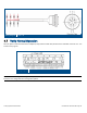

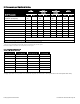
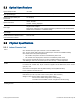


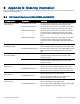
Table Of Contents
- 1 Introduction
- 2 Installation Guidelines
- 3 HX Indoor Physical Installation
- 4 HX Outdoor Physical Installation
- 5 Appendix A: System Specifications
- 6 Appendix B: Ordering Information
- 7 Appendix C: HX Outdoor Non-Standard Connector Descriptions
- 8 Appendix D: Power Cable Specifications

Corning Optical Communications User Manual I CMA-066-AEN I Page 52
Wiring Diagram
Figure 4-12
4.7 Verify Normal Operation
After the power connections have been completed, verify that the Power LED (located on the underside of the HX unit – see
section
1.5.2) is green.
Wiring Diagram
Figure 4-13
Note: The HX monitoring and management capabilities are performed via the host OCH unit. Refer to the SC-450 User
Manual for the configuration and management options.