
User's Manual

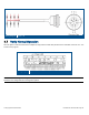

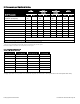


Table Of Contents
- 1 Introduction
- 2 Installation Guidelines
- 3 HX Indoor Physical Installation
- 4 HX Outdoor Physical Installation
- 5 Appendix A: System Specifications
- 6 Appendix B: Ordering Information
- 7 Appendix C: HX Outdoor Non-Standard Connector Descriptions
- 8 Appendix D: Power Cable Specifications

Corning Optical Communications User Manual I CMA-066-AEN I Page 51
4.6.3.2 DC Power Input Model Connections
Note: Refer to Appendix D for the HX OD DC power cable specifications.
General Information
• Length and tolerance of DC wire varies depending on ordered cable. See Table 4-2.
P/N
Length (Meter)
Tolerance (Meter)
705A030841 2 ± 0.1
705A030821 5 ± 0.5
705A030851 10 ± 0.1
705A030801 50 ± 0.5
705A030811 100 ± 0.5
705A030831 200 ± 0.5
Table 4-2. P/N and Length Table
• DC Input: 25-48 VDC
• No. of DC connector conductors: 8 (all four pairs are connected together – splitting the power evenly between them)
• DC Conductor size: 20 AWG
• At least 8A slow blow fuse
Connection Pinout
Connect the power cable wires according to the wire connection in Table 4-3 and Figure 4-12.
Wire Color
AWG
PIN
First Couple Red 20 A
Black 20 B
Second Couple Red 20 C
Black 20 D
Third Couple Red 20 E
Black 20 F
Fourth Couple Red 20 G
Black 20 H
Table 4-3. Wire Connections