
User's Manual
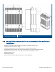

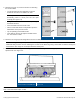
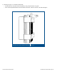


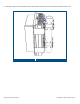
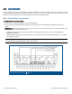


Table Of Contents
- 1 Introduction
- 2 Installation Guidelines
- 3 HX Indoor Physical Installation
- 4 HX Outdoor Physical Installation
- 5 Appendix A: System Specifications
- 6 Appendix B: Ordering Information
- 7 Appendix C: HX Outdoor Non-Standard Connector Descriptions
- 8 Appendix D: Power Cable Specifications

Corning Optical Communications User Manual I CMA-066-AEN I Page 48
4.6 Connections
The HX Outdoor connections are performed from the underside of the HX unit after it has been mounted. The main
connections include the RF, fiber and power connections. These connectors are waterproof and are protected by covers
when not connected. Remove the connector waterproof covers when connecting cables.
4.6.1 RF and Fiber Connections
To connect the RF and fiber cables
1. Connect the RF antenna coax cable to the HX ANTENNA port.
2. Connect the (Corning OptiTap®) fiber cable to the HX F/O UPLINK and F/O DOWNLINK OptiTap® connectors as
follows:
IMPORTANT! OptiTap™ pullout force ranges from a few lbs to 50+ lbs with the dust cap or connector installed. This
prevents damages caused to the DAS unit.
• Downlink: Connect the fiber optic cable from splice box, leading from the OCH port, to the corresponding F/O
DOWNLINK OptiTap®.
• Uplink: Connect the fiber optic cable from splice box, leading from the HX F/O UPLINK OptiTap® port, to the uplink
port leading to the OCH.
Note: Keep in mind the rules for handling and connecting F/O cables. The F/O cables will be connected to the
associated OCH in the communication room at a later phase.
HX RF and Fiber Connectors
Figure 4-9