
User's Manual
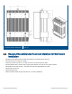

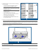
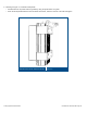


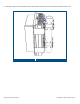
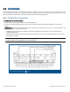


Table Of Contents
- 1 Introduction
- 2 Installation Guidelines
- 3 HX Indoor Physical Installation
- 4 HX Outdoor Physical Installation
- 5 Appendix A: System Specifications
- 6 Appendix B: Ordering Information
- 7 Appendix C: HX Outdoor Non-Standard Connector Descriptions
- 8 Appendix D: Power Cable Specifications

Corning Optical Communications User Manual I CMA-066-AEN I Page 46
5. Lift the HX Unit and fit the clamp bolts into the four middle holes of each bracket, as shown in Figure 4-7:
• Top pole clamp bolts into top middle HX bracket holes
• Bottom pole clamp bolts into bottom middle HX bracket holes
Note: Brush ring (see Figure
4-7) is intended for the purpose of lifting the HX unit. However, it can also be used for
additional safety measure such as hanging the HX unit via the brush ring using a steel cable of sufficient strength and
tying it to an iron bar of enough strength.
Mounting HX OD Unit on Pole Clamp
Figure 4-7