
User's Manual
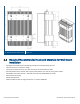

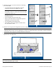
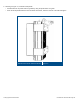


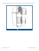
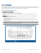


Table Of Contents
- 1 Introduction
- 2 Installation Guidelines
- 3 HX Indoor Physical Installation
- 4 HX Outdoor Physical Installation
- 5 Appendix A: System Specifications
- 6 Appendix B: Ordering Information
- 7 Appendix C: HX Outdoor Non-Standard Connector Descriptions
- 8 Appendix D: Power Cable Specifications

Corning Optical Communications User Manual I CMA-066-AEN I Page 43
2. Referring to Figure 4-4, insert the anchors for mounting
the unit as follows:
• Use the provided four hole template to mark the
location of the holes to be drilled in the wall.
Note: Key holes are 300 mm apart from each other
horizontally (center to center) and 372
mm apart
vertically (see Figure
4-3).
• Using a hammer drill, drill 5/8” holes for expanding
lead shield anchors.
• Clean the debris from the anchor holes.
• Fill the 4 holes with silicon to help weather-proof the
drilled holes and to prevent erosion.
• Tap in expanding lead shield anchors
• Insert bolts in anchors and tighten until bolt head is
0.5” from surface of wall.
Inserting Anchors
Figure 4-4
3. Mount the HX using key-hole designations onto the four bolts.
Note: Brush ring (see Figure
4-3) is intended for the purpose of lifting the HX unit. However, it can also be used for
additional safety measure such as tethering the HX unit via the brush ring using a steel cable of sufficient strength to
withstand the units’ weight to an adequate alternate anchor point.
4. Reach behind the mounting bracket and tighten the 4 wall mount lag bolts with an appropriate size wrench, socket or
speed wrench. See Figure
4-5.
Bracket Holes for Wall Mount
Figure 4-5
Note 1: If it is determined that a washer is needed for a secure installation the washer should not be more than 20 mm OD.
Note 2: Recommended torque = 8 ft/lb