
User's Manual


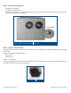
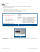
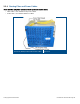


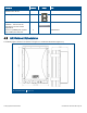
Table Of Contents
- 1 Introduction
- 2 Installation Guidelines
- 3 HX Indoor Physical Installation
- 4 HX Outdoor Physical Installation
- 5 Appendix A: System Specifications
- 6 Appendix B: Ordering Information
- 7 Appendix C: HX Outdoor Non-Standard Connector Descriptions
- 8 Appendix D: Power Cable Specifications

Corning Optical Communications User Manual I CMA-066-AEN I Page 40
Description
Quantity
Image
P/N
Boot, straight, lipped, fluid-resistant
elastomer 23 to 10 mm
1
634A004501
Pole Clamp 4
264A088302
HX, Outdoor, Profile for wall
installation – iron bar used for
protecting the HX from vertical
displacement
1
264A174201
Anchor nut (JUMBO),HEX 1/2,NUT
7/16,L=60mm,inner 5/16, SS
2
631A004601
4.3 HX Outdoor Dimensions
The following figures show the HX Outdoor unit Figure 4-1 and bracket dimensions (Figure 4-2).
HX Unit Dimensions
Figure 4-1