
User's Manual


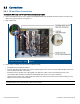
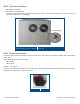
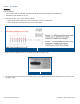
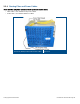


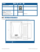
Table Of Contents
- 1 Introduction
- 2 Installation Guidelines
- 3 HX Indoor Physical Installation
- 4 HX Outdoor Physical Installation
- 5 Appendix A: System Specifications
- 6 Appendix B: Ordering Information
- 7 Appendix C: HX Outdoor Non-Standard Connector Descriptions
- 8 Appendix D: Power Cable Specifications

Corning Optical Communications User Manual I CMA-066-AEN I Page 35
3.3.3.2 DC Models
DC Wiring
Note the following:
• The HX Indoor (DC model) 18 pin DC Input terminal block connector supports 20-30 AWG wires
• Maximum current allowed per pin: 5 A
1. Referring to Figure
3-13, connect wires as follows:
• Higher voltage wires from the DC source to RED wires of the DC cable jumper.
• Lower voltage wires to the BLACK wires of the cable jumper.
18-pair DC Cable and Connector Diagram
Figure 3-10
2. Connect the DC cable jumper to ‘DC in’ power connector (see Figure 3-11).
DC Connector
Figure 3-11
3. A voltmeter should read +48V when it’s negative side is connected to the black wire and positive side to red wire of the
HX jumper cable.