
User's Manual


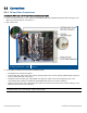
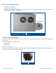
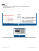
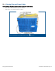


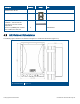
Table Of Contents
- 1 Introduction
- 2 Installation Guidelines
- 3 HX Indoor Physical Installation
- 4 HX Outdoor Physical Installation
- 5 Appendix A: System Specifications
- 6 Appendix B: Ordering Information
- 7 Appendix C: HX Outdoor Non-Standard Connector Descriptions
- 8 Appendix D: Power Cable Specifications

Corning Optical Communications User Manual I CMA-066-AEN I Page 33
3.3 Connections
3.3.1 RF and Fiber Connections
Connect the HX Indoor unit RF and Fiber connections as follows
1. Connect broadband antenna coax to (duplexed) ANTENNA PORT (two for MIMO models) located on the right of the
cabinet front panel (external). See Figure
3-7.
2. Open cabinet door.
HX Indoor Connections – SISO
Figure 3-7
3. Connect fiber as follows (two connections for MIMO models):
• Install splice box near Remote Cabinet.
• Connect fiber optic cable to splice box and the SC/APC pigtails to the HX RHU module (MIMO models include two
service modules with fiber connections).
• Downlink: Connect the fiber optic cable pigtails from splice box, which comes from the BU/OCH port, to the
corresponding RHU SC/APC TO BASE and FROM BASE optic ports of the service module(s).
• Uplink: Connect the fiber optic cable pigtails from splice box, which comes from the RHU service module(s), to the
uplink port that connects to the BU/OCH.
Note: Keep in mind the rules for handling and connecting F/O cables. The F/O cables will be connected to the
associated OCH in the communication room at a later phase.