
User's Manual


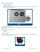
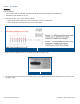
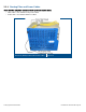


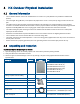
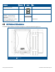
Table Of Contents
- 1 Introduction
- 2 Installation Guidelines
- 3 HX Indoor Physical Installation
- 4 HX Outdoor Physical Installation
- 5 Appendix A: System Specifications
- 6 Appendix B: Ordering Information
- 7 Appendix C: HX Outdoor Non-Standard Connector Descriptions
- 8 Appendix D: Power Cable Specifications

Corning Optical Communications User Manual I CMA-066-AEN I Page 31
2. Referring to Figure 3-5, prepare the
appropriate anchors in wall:
• Using the bracket keyholes as guides,
mark the location of the four holes (two per
bracket) to be drilled in the wall. See
Figure
3-4 – dimension in mm).
• Using a hammer drill, drill holes for
expanding lead shield anchors. Refer to
Figure
3-4 for keyhole dimensions.
• Clean the debris from the anchor holes.
• Fill the 4 holes with silicon to help
weather-proof the drilled holes and to
prevent erosion.
• Tap in expanding lead shield anchors
• Insert bolts in anchors and tighten until
bolt head is 0.5” from surface of wall.
3. Mount the HX using key-hole designations
onto the 4 bolts. See Figure
3-6.
4. Tighten the 4 wall mount lag bolts with an
appropriate size wrench, socket or speed
wrench.
Wall Mount Bracket Keyhole Dimensions
Figure 3-4
Inserting Anchors
Figure 3-5