
User's Manual
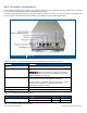
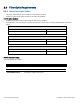
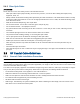

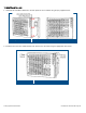
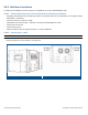
Table Of Contents
- 1 Introduction
- 2 Installation Guidelines
- 3 HX Indoor Physical Installation
- 4 HX Outdoor Physical Installation
- 5 Appendix A: System Specifications
- 6 Appendix B: Ordering Information
- 7 Appendix C: HX Outdoor Non-Standard Connector Descriptions
- 8 Appendix D: Power Cable Specifications

Corning Optical Communications User Manual I CMA-066-AEN I Page 30
3.2.3 Wall-Mount Installation
The wall-mount installation procedure references an installation on concrete walls/solid block walls.
3.2.3.1 Required/Recommended Tools and Materials for Wall Mount Installation
• Expanding lead shield anchors with 3/8” lag bolt with hex head bolts should be used (McMaster-Carr catalogue number
92403A200, or equivalent).
• Hex bolts need to be at least 3” in length
• Kobalt 3/8-in Drive Click 20 Ft-lbs - 100 Ft-lbs Torch Wrench Model #85601 or similar
• Kobalt Crows foot wrench
• Kobalt ratching wrench
• M18™ Cordless Lithium-Ion High-Performance ½” Hammer Drill/Driver
3.2.3.2 Mounting HX on Wall
Note: The HX unit should be mounted on concrete/hollow block walls only.
1. Assemble each wall-mount bracket to the side of the of the cabinet rear panel using the 8-32X1/2,PAN, HD, Philips, Flat
screws and washers (four per bracket). See Figure
3-3.
HX Indoor Unit with Assembled Wall-Mount Brackets
Figure 3-3