
User's Manual
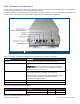

Table Of Contents
- 1 Introduction
- 2 Installation Guidelines
- 3 HX Indoor Physical Installation
- 4 HX Outdoor Physical Installation
- 5 Appendix A: System Specifications
- 6 Appendix B: Ordering Information
- 7 Appendix C: HX Outdoor Non-Standard Connector Descriptions
- 8 Appendix D: Power Cable Specifications
Corning Optical Communications User Manual I CMA-066-AEN I Page 26
2.5.4 Cable Routing
Ensure all cables, e.g. power cable, feeder cable, optic fiber, commissioning cable, connecting are properly routed and
secured so that they are not damaged.
2.6 Antenna Specifications and Guidelines
Determine the antenna installation configuration, according to the transmission and coverage requirements and the
installation site conditions.
2.6.1 Authorized Antennas and Couplers
• External antennas - No limitation on any vendor of available external antennas with respect to the following
requirements:
• Omni Directional or Directional
• Supported frequency range: wideband antennas supporting a range of 700 MHz to 2600 MHz
• Gain: up to 12.5 dBi
• Impedance: 50 Ohm
• Types of couplers/splitters – depends on number of splits
• Couplers – Use N-Male to N-Female broadband coupler separately ordered from Corning (P/N AK-1COUPLER-NM-
NF) or the equivalent:
• Broadband frequency: 698 – 2700 MHz
• -40 dB coupling (QMA coupling port)
• Max. VSWR/Return Loss (dB): 1.15:1/-23.0
• Max. Insertion Loss (dB): 0.2
• Impedance: 50 ohms
2.6.2 General Antenna Installation Guidelines
• The wideband antenna should be installed at a convenient location, free of metallic obstruction (can also be installed in
plenum spaces).
• Install the connected antenna at the designated height and tune it roughly toward the Service coverage area.
• Each individual antenna used for this transmitter must be installed to provide the separation distance as specified in the
FCC grant from all persons during normal operation and must not be co-located with any other antenna for meeting RF
exposure requirements
2.7 Grounding Requirement
Verify that the equipment has been well grounded (refer to the grounding lug on the bottom port panel of the HX Outdoor or
on the rear panel of the HX Indoor). This includes antennas and all cables connected to the system. Ensure lightning
protection for the antennas is properly grounded. Also, see sections
3.3.2 (HX Indoor) and 4.6.2 (HX Outdoor).
2.8 Manual Handling
During transportation and installation, take necessary handling precautions to avoid potential physical injury to the
installation personnel and the equipment.