
User's Manual
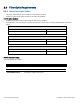
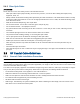
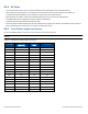

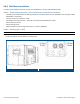
Table Of Contents
- 1 Introduction
- 2 Installation Guidelines
- 3 HX Indoor Physical Installation
- 4 HX Outdoor Physical Installation
- 5 Appendix A: System Specifications
- 6 Appendix B: Ordering Information
- 7 Appendix C: HX Outdoor Non-Standard Connector Descriptions
- 8 Appendix D: Power Cable Specifications

Corning Optical Communications User Manual I CMA-066-AEN I Page 25
2.5.2 RF Rules
• Use coax RG-223, 50 ohm, for RF connections between HX Indoor/Outdoor units and DAS antennas.
• When using the Corning system in an environment in which other indoor coverage systems are installed, it is
recommended (where possible) that the antennas are placed at least two meters apart
• When bending coax cables, verify that the bending radius does not exceed the coax specifications.
• Use wideband antennas supporting a range of 700 MHz to 2600 MHz
• Terminate all unused HX RF ports with a 50 ohm load
• Make sure that the VSWR measured at the coax cable meets the product specification The VSWR must be measured
prior to terminating the HX RF ports in the remote communication rooms.
2.5.3 Coax Cable Lengths and Losses
Use the compatible jumper to connect the coax connector to the external antenna.
Note: The required distance between the antennas (installed in the ceiling) depends on the infrastructure and calculated
path-loss.
Table 2-1. Typical Coax Cable Lengths and Losses
Coax Length
Coax Loss
(900 MHz)
Connector
Loss
Total Loss
30 0.7 1.5 2.2
40 0.9 1.5 2.4
50 1.1 1.5 2.6
60 1.3 1.5 2.8
70 1.5 1.5 3
80 1.7 1.5 3.2
90 1.9 1.5 3.4
100 2.1 1.5 3.6
110 2.3 1.5 3.8
120 2.5 1.5 4
130 2.7 1.5 4.2
140 2.9 1.5 4.4
150 3.1 1.5 4.6
160 3.3 1.5 4.8
170 3.5 1.5 5
180 3.7 1.5 5.2
190 3.9 1.5 5.4
200 4.1 1.5 5.6