
User's Manual
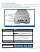
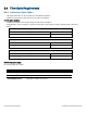
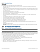

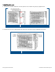
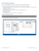
Table Of Contents
- 1 Introduction
- 2 Installation Guidelines
- 3 HX Indoor Physical Installation
- 4 HX Outdoor Physical Installation
- 5 Appendix A: System Specifications
- 6 Appendix B: Ordering Information
- 7 Appendix C: HX Outdoor Non-Standard Connector Descriptions
- 8 Appendix D: Power Cable Specifications

Corning Optical Communications User Manual I CMA-066-AEN I Page 21
1.5.2 HX Outdoor Unit Interfaces
The HX Outdoor interfaces are located on the underside panel of the unit (connectors face down when unit is mounted).
The unit interfaces include the RF, power and optical link connectors.
The power, RS232 and F/O connectors are special weather resistant connectors. You may either order ready cables from
Corning or refer to the manufacturer Part Numbers for generating the required cables (Appendix C).
HX Outdoor Interfaces
Figure 1-10
Table
1-5 and Table 1-6 provide a description of the HX Outdoor type connectors and LEDs.
Connector
Description
Antenna N-Type female 50Ω duplexed connector for RF antenna
F/O Uplink and Downlink Corning OptiTap® fiber-optic waterproof connectors for either
SM
IMPORTANT!
OptiTap™ pullout force ranges from a few lbs to
50+ lbs with the dust cap or connector installed. This prevents
damages caused to the DAS unit.
AC or DC PWR (model dependent) Local Power (AC): -20UNEF, plug, 3-pin waterproof, solder for
panel, power connector for 100/240 VAC power feed
Remote DC Power: 1-20UNEF, plug, 8-pin waterproof , solder
for panel, power connector for 25-48 VDC power feed
Max Power Consumption: 340 W
RS-232 One 10-pin RS232 waterproof connector for local craft
Grounding Lug Two hole, standard barrel grounding lug (LCD10-14A-L Panduit)
Table 1-5. HX Outdoor Connector Descriptions
LED
Description
Color
Status
Power Device is powered Green Steady On
Power not supplied to the unit Green Off
Table 1-6: HX Outdoor PWR LED Description