
User's Manual


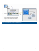

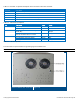
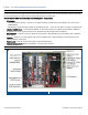
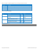
Table Of Contents
- 1 Introduction
- 2 Installation Guidelines
- 3 HX Indoor Physical Installation
- 4 HX Outdoor Physical Installation
- 5 Appendix A: System Specifications
- 6 Appendix B: Ordering Information
- 7 Appendix C: HX Outdoor Non-Standard Connector Descriptions
- 8 Appendix D: Power Cable Specifications

Corning Optical Communications User Manual I CMA-066-AEN I Page 20
Table 1-3 and Table 1-4 provide descriptions of the HX indoor type connectors and LEDs.
Connector
Description
F/O SC/APC fiber-optic connector for either SM fibers (1 for each RF service module)
Antenna N-Type female 50Ω duplexed connector for RF antenna (MIMO1 and MIMO2)
AC PWR 100/240 VAC; 50/60 Hz; 8A Slow Blow Fuse
DC PWR 18 pin power connector for 25-48V DC power feeds
RS-232 Local craft connector
Table 1-3. Connector Descriptions
Name
Description
Color
Status
Power Device is powered Green Steady On
Power not supplied to the unit Green Off
Comm When connected and discovered by an
OPTM (BU)
Green Blink per communication
attempt
When device is powered on but no
external communication is received
Green Steady Slow Blink
Link No Optical link is present Green Off
Low optical link level from OPTM Green Blink
Normal optical link level from OPTM Green Steady On
Table 1-4. LED Descriptions
Note: LEDs are the same for each RF module.