
User's Manual


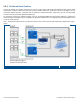

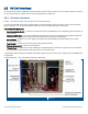
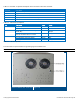
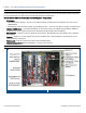
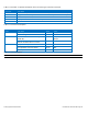
Table Of Contents
- 1 Introduction
- 2 Installation Guidelines
- 3 HX Indoor Physical Installation
- 4 HX Outdoor Physical Installation
- 5 Appendix A: System Specifications
- 6 Appendix B: Ordering Information
- 7 Appendix C: HX Outdoor Non-Standard Connector Descriptions
- 8 Appendix D: Power Cable Specifications

Corning Optical Communications User Manual I CMA-066-AEN I Page 19
1.5.1.2 HX Indoor MIMO Internal and Front Interfaces
Note: HX-5 units include SISO models only.
The two HX Indoor antenna ports are located externally. All other interfaces such as F/O connections, power connections,
etc. are located inside the cabinet and are accessed by opening the cabinet door.
The HX Indoor MIMO model includes the following main components:
• RF Modules:
• Quad-band Service Module – connects to the Base Unit using a single fiber pair and supports up to four services
(SISO/MIMO1)
• Additional RF module providing support for two MIMO2 services – connects to the Base Unit using a single fiber pair
• External Amplifier Blade – Two External Amplifiers are mounted on each of the 2 blades and provide the additional
amplification on the DL signals coming from the Quad-band Service Module top the Multiplexer
• 8:1 Multiplexer – combines UL and DL signals of the four bands, while providing the proper filtering, into a duplexed
antenna port
• Duplexer - combines UL and DL signals of the Stream 2 MIMO bands , while providing the proper filtering, into the
MIMO2 duplexed antenna port
• Power supply – local AC or Remote DC power feed (model dependent)
• Duplexed Antenna Ports (MIMO1 and MIMO2) – interface to RF antennas
Note: Detailed descriptions of the components and LEDs are provided Table
1-3 and Table
1-4.
Example of HX Indoor MIMO Remote Unit Internal View (Front)
Figure 1-9