
User's Manual


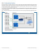

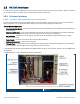
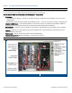
Table Of Contents
- 1 Introduction
- 2 Installation Guidelines
- 3 HX Indoor Physical Installation
- 4 HX Outdoor Physical Installation
- 5 Appendix A: System Specifications
- 6 Appendix B: Ordering Information
- 7 Appendix C: HX Outdoor Non-Standard Connector Descriptions
- 8 Appendix D: Power Cable Specifications

Corning Optical Communications User Manual I CMA-066-AEN I Page 17
1.5 HX Unit Interfaces
The HX antenna port (two for MIMO) is located externally. All other interfaces such as F/O connections, power connections,
etc. are located inside the cabinet and are accessed by opening the cabinet door.
1.5.1 HX Indoor Interfaces
1.5.1.1 HX Indoor SISO Internal and Front Panel Interfaces
The HX Indoor ANTENNA port (two for MIMO models) is located externally. All other interfaces such as F/O connections,
power connections, etc. are located inside the cabinet and are accessed by opening the cabinet door.
The HX Model Components:
• Quad-band Service Module – Connects to the optical converter unit (BU/OCH) using a single fiber pair and supports up
to four services
• External Amplifier Blade – Two External Amplifiers are mounted on each of the two blades and provide the additional
amplification on the DL signals coming from the Quad-band Service Module to the Multiplexer
• 8:1 Multiplexer – Combines UL and DL signals of the four bands, while providing the proper filtering, into a single
duplexed antenna port
• Power Supply – Local AC or Remote DC power feed (model dependent)
• Duplexed Antenna Port *– Interface to RF antennas
• **Coupler Ports – Coupler ports used for enabling the user/field engineer to measure the signals at the remote without
disconnecting the antenna cable and affecting services on the main stream.
* Upgradeable SISO models include MIMO1 and MIMO2 duplex RF ports and craft ports, however only the MIMO1 ports
are applicable.
** Model dependant – refer to Ordering Information in Appendix B.
Example of Indoor HX Remote Unit Interfaces – Front View
Figure 1-7