
User's Manual


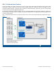

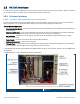
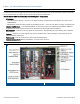
Table Of Contents
- 1 Introduction
- 2 Installation Guidelines
- 3 HX Indoor Physical Installation
- 4 HX Outdoor Physical Installation
- 5 Appendix A: System Specifications
- 6 Appendix B: Ordering Information
- 7 Appendix C: HX Outdoor Non-Standard Connector Descriptions
- 8 Appendix D: Power Cable Specifications

Corning Optical Communications User Manual I CMA-066-AEN I Page 12
1.2 System Architecture
HX mid-power remote unit compliments the MA1000 or MA2000 system, providing a complete solution consisting of HX
remote units at the remote locations and headend elements that are shared with any other MA1000 or MA2000 system
remotes that are either installed or being installed at the site. HX4/HX5 units can be optically daisy chained to other HX
units supporting different bands (e.g. WCS and 2500 MHz TDD) for further band coverage needs.
In the downlink, at the headend, the BTS or BDA signal is conditioned by the RIU, ensuring a constant RF level. The
conditioned signal is then converted by an optical converter unit (i.e. base unit) to an optical signal to transport over single-
mode fiber to the HX remote units, which are located at the remote locations. In the uplink, the process is reversed.
The system controller (SC-450) enables local and remote management, as well as controls all MA1000, MA2000 and HX
elements from a single, centralized location.
The HX remote unit consists of a compact enclosure that houses the RF module, power elements and the required
interfaces. The RF module supports various configurations of three (International models), four and five bands.
Note: HX-5 units are SISO only.
All mobile services are combined and distributed through a single antenna port over antennas installed at the remote
locations.
Example of SISO Architecture with HX4 Indoor, HX WCS, and HX5 Outdoor
Figure 1-2