
User's Manual


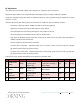


Table Of Contents
- Warranties
- Hardware
- Software Warranty
- Returns
- Limitations of Liabilities
- Reporting Defects
- Warnings and Admonishments
- RF Safety
- Compliance with RF safety requirements:
- Power requirements for DC Inputs
- Laser Safety
- Care of Fiber Optic Connectors
- Regulatory Compliance Information
- Standards and Certifications
- Licensee Contact Information
- About this Guide
- Additional Relevant Documents
- List of Acronyms
- Table of Contents
- 1 Introduction
- 2 Installation Guidelines
- 3 Physical Installation
- Appendix A: System Specifications
- RF Parameters
- Supported Services
- RF Parameters per Service Antenna Port
- RF Adjustment
- OverPower Protection Mechanism
- Power Down Mechanism
- RF Parameters for External Wideband and WCS Input Ports
- Physical Specifications
- Standards and Approvals
- Appendix B: Ordering Information

Corning Restricted - Draft for public release
Appendix A: System Specifications
CMA-XXX-AEN
Page 54
OverPower Protection Mechanism
HX 2.5GHz-TDD have limiter mechanism in order to limit and maintain the output level to level.
DL limiter threshold shall be the same as “Max output target” value and the range shall be at least 6dB.
To prevent HX 2.5GHz-TDD UNIT system from damage due to output over power, an automatic shutdown mechanism shall be
implemented into the HX 2.5GHz-TDD UNIT and it shall continuously monitor its output power.
Overpower criteria - In case DL output power is higher than Max output power by more than 3dB for more than 5 seconds or HX
2.5GHz-TDD UNIT Overpower state identified - unit shall turn off service in order to prevent damage.
Recovery from overpower protection shall occur by estimating Output RF power by measuring input power and taking
attenuation status into account. If estimated output power is < (Max output power -3) than service shall be recovered.
Power Down Mechanism
• Over Current Protection ( OCP)
In order to avoid danger from overcurrent due to output load failure or short-circuit, over current protection is triggered at the
range above 110% of maximum output current in which turns the power to output current down. It will automatically recover the
current at normal current range (below 100% current load). (RCU + 12V)
In case of SLOT1 and SLOT2, E-FUSE mechanism blocks the current. (3.3A~3.6A/Each mechanism works independently.) and must
be recovered by actuating signal of RCU.
• Over Voltage Protection (OVP)
When output current are being operated above the rated voltage within the range of input current, over voltage protection are
triggered at 110% ~ 140% of rated output voltage and the device is shut down.
•
Input Terminal Circuit Protection
This circuit protects the PSU from being damaged by the over current when inverse polarity are connected to the input terminal.
• Short Circuit Protection(SCP)
Even if circuits are shorted while in operation, short circuit protection protects semiconductor devices within and in case of
SLOT1, SLOT2, E-FUSE mechanism blocks the current(3.3A~3.6A/Each mechanism works independently.) and must be recovered
by actuating signal of RCU.
RF Parameters for External Wideband and WCS Input Ports
RF Parameters Wideband RU Inport Port WCS Input Port
Frequency Range
698 – 2170 MHz
2305 – 2360 MHz
Insertion Loss
0.6 dB 0.8 dB
Isolation
50 dB Min.@ 2496-2690 MHz 50 dB Min.@ 2496~2690 MHz
Return Loss
15 dB Min. 16 dB Min.
Power Rating
Avg.100 W Avg.100 W