
User's Manual

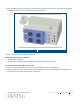


Table Of Contents
- Warranties
- Hardware
- Software Warranty
- Returns
- Limitations of Liabilities
- Reporting Defects
- Warnings and Admonishments
- RF Safety
- Compliance with RF safety requirements:
- Power requirements for DC Inputs
- Laser Safety
- Care of Fiber Optic Connectors
- Regulatory Compliance Information
- Standards and Certifications
- Licensee Contact Information
- About this Guide
- Additional Relevant Documents
- List of Acronyms
- Table of Contents
- 1 Introduction
- 2 Installation Guidelines
- 3 Physical Installation
- Appendix A: System Specifications
- RF Parameters
- Supported Services
- RF Parameters per Service Antenna Port
- RF Adjustment
- OverPower Protection Mechanism
- Power Down Mechanism
- RF Parameters for External Wideband and WCS Input Ports
- Physical Specifications
- Standards and Approvals
- Appendix B: Ordering Information

Corning Restricted - Draft for public release
Physical Installation
CMA-XXX-AEN
Page 35
5. Hang the unit and bracket assembly onto the two bolts using the key holes.
6. Insert remaining bolts (two on each side) through remaining bracket holes into anchor.
7. Tighten all four bolts.
8. Verify that HX 2.5 GHz TDD unit is tightly secured and does not shake.
Refer to Figure
3-8 for HX 2.5 GHz TDD wall-mount examples with additional MA2000 remote.
Example of HX 2.5 GHz TDD with Assembled EPM Alongside MA2000 TSX Remote
Figure 3-8
3.2.3.3 Vertical Wall Mount Installation
The vertical wall-mount brackets are optional and ordered separately.