
User's Manual

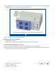


Table Of Contents
- Warranties
- Hardware
- Software Warranty
- Returns
- Limitations of Liabilities
- Reporting Defects
- Warnings and Admonishments
- RF Safety
- Compliance with RF safety requirements:
- Power requirements for DC Inputs
- Laser Safety
- Care of Fiber Optic Connectors
- Regulatory Compliance Information
- Standards and Certifications
- Licensee Contact Information
- About this Guide
- Additional Relevant Documents
- List of Acronyms
- Table of Contents
- 1 Introduction
- 2 Installation Guidelines
- 3 Physical Installation
- Appendix A: System Specifications
- RF Parameters
- Supported Services
- RF Parameters per Service Antenna Port
- RF Adjustment
- OverPower Protection Mechanism
- Power Down Mechanism
- RF Parameters for External Wideband and WCS Input Ports
- Physical Specifications
- Standards and Approvals
- Appendix B: Ordering Information

Corning Restricted - Draft for public release
Physical Installation
CMA-XXX-AEN
Page 32
3. Place the EPM onto the top of the HX 2.5 GHz TDD unit and using six UNC 6-32, 11 mm screws (not provided),
assemble the EPM onto the HX 2.5 GHz TDD unit. See Figure
3-4.
EPM and HX 2.5 GHz TDD Assembly
Figure 3-4
3.2.3.2 Horizontal Wall Mount Installation
Additional required tools and materials
• Philips/electric screwdriver
• Four anchors for mounting brackets on wall (anchor type depends on surface type)
To mount the HX 2.5 GHz TDD unit on the wall:
1. Remove the factory assembled rack brackets from the sides of the HX 2.5 GHz TDD unit.
2. Using ten UNC 6-32, 12 mm screws for each bracket (provided in HX kit), assemble the wall-mount brackets to
the sides of the HX 2.5 GHz TDD as shown in Figure
3-5.