
User's Manual


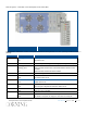


Table Of Contents
- Warranties
- Hardware
- Software Warranty
- Returns
- Limitations of Liabilities
- Reporting Defects
- Warnings and Admonishments
- RF Safety
- Compliance with RF safety requirements:
- Power requirements for DC Inputs
- Laser Safety
- Care of Fiber Optic Connectors
- Regulatory Compliance Information
- Standards and Certifications
- Licensee Contact Information
- About this Guide
- Additional Relevant Documents
- List of Acronyms
- Table of Contents
- 1 Introduction
- 2 Installation Guidelines
- 3 Physical Installation
- Appendix A: System Specifications
- RF Parameters
- Supported Services
- RF Parameters per Service Antenna Port
- RF Adjustment
- OverPower Protection Mechanism
- Power Down Mechanism
- RF Parameters for External Wideband and WCS Input Ports
- Physical Specifications
- Standards and Approvals
- Appendix B: Ordering Information

Corning Restricted - Draft for public release
Introduction
CMA-xxx-AEN
Page 20
Module LED Description
PSU Run Steady green – required power input detected
Off – no power input
PSU Off – normal operation
Steady red – faulty PSU module; In more than 10%
difference than the rated DC output, the red LED occurs.
HX-2.5 GHz
TDD Module
Link Off – No optical link
Blinking green – Low optical link level
Steady green – Normal optical link level
Run Off – no power input
Blinking green – power input detected
Table 1-4. HX 2.5 GHz TDD PSU and Module LEDs
1.5 External Passive Module (EPM)
The external passive module (EPM) is required when in installations with an existing MA1000/MA2000 remote unit (e.g.
MA2000 QX). The EPM is used to combine up to four low band output wideband signals with the high band HX 2.5
GHz TDD output signal. The module includes a 1:4 splitter for the high band (i.e. 2.5 GHz TDD) and four internal
diplexers that combine the 2.5 GHz TDD signal with the wideband signal received from the MA1000/MA2000 remote.
The EPM interfaces to the HX 2.5 GHz TDD and to the service combiner unit (SCU) of the MA1000/MA2000 remote.
External Passive Module – Front (Top) and Rear (Bottom) Panels
Figure 1-9
Refer to Table 1-5 for a description of the EPM interfaces.
Panel Connector Description
Front HIGH I/O One Mini DIN 4.3-10 high-
band input port interfaces to
additional HX or MA1000/MA2000 remote
Rear ANT Four Mini DIN 4.3-10 c
ombined output ports interface to
wideband antennas
LB Four N-Type low-band input ports interface to service combiner
unit (SCU) on MA1000/MA2000