
User's Manual


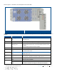


Table Of Contents
- Warranties
- Hardware
- Software Warranty
- Returns
- Limitations of Liabilities
- Reporting Defects
- Warnings and Admonishments
- RF Safety
- Compliance with RF safety requirements:
- Power requirements for DC Inputs
- Laser Safety
- Care of Fiber Optic Connectors
- Regulatory Compliance Information
- Standards and Certifications
- Licensee Contact Information
- About this Guide
- Additional Relevant Documents
- List of Acronyms
- Table of Contents
- 1 Introduction
- 2 Installation Guidelines
- 3 Physical Installation
- Appendix A: System Specifications
- RF Parameters
- Supported Services
- RF Parameters per Service Antenna Port
- RF Adjustment
- OverPower Protection Mechanism
- Power Down Mechanism
- RF Parameters for External Wideband and WCS Input Ports
- Physical Specifications
- Standards and Approvals
- Appendix B: Ordering Information

Corning Restricted - Draft for public release
Introduction
CMA-xxx-AEN
Page 16
1.4 HX Unit Description
The HX 2.5GHz TDD unit consists of the following main modules:
• RCU – Remote control unit; Includes status LEDs for each module and control ports
• ANT (MUX) – Multiplexer [ANT. 1 MUX (right) for SISO; ANT. 2 MUX (left) for MIMO] including interfaces to HX
WCS, HX4 and RF antennas/MA1000/MA2000 units (via EPM); combines signal sources additional external RF
signals (when connected to HX unit and MA1000/MA2000 remote) while providing the proper filtering into a single
antenna port
• Module – [ANT. 1 (right) for SISO; ANT. 2 (left) for MIMO] Internal module that interfaces to the optical converter
unit (OCH) connects via a single mode fiber pair and supports one service. The HX 2.5 GHz TDD module provides
the additional amplification on the DL signals routed from the OCH towards the multiplexer.
• Power Supply - DC power; Internal module
The unit plot plan is provided on the left side of the enclosure door:
HX 2.5 GHz TDD Unit Plot Plan
Figure 1-5
The following sections provide details on the front panel and internal module interfaces.