
User's Manual


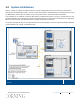

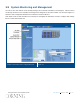


Table Of Contents
- Warranties
- Hardware
- Software Warranty
- Returns
- Limitations of Liabilities
- Reporting Defects
- Warnings and Admonishments
- RF Safety
- Compliance with RF safety requirements:
- Power requirements for DC Inputs
- Laser Safety
- Care of Fiber Optic Connectors
- Regulatory Compliance Information
- Standards and Certifications
- Licensee Contact Information
- About this Guide
- Additional Relevant Documents
- List of Acronyms
- Table of Contents
- 1 Introduction
- 2 Installation Guidelines
- 3 Physical Installation
- Appendix A: System Specifications
- RF Parameters
- Supported Services
- RF Parameters per Service Antenna Port
- RF Adjustment
- OverPower Protection Mechanism
- Power Down Mechanism
- RF Parameters for External Wideband and WCS Input Ports
- Physical Specifications
- Standards and Approvals
- Appendix B: Ordering Information

Corning Restricted - Draft for public release
Introduction
CMA-xxx-AEN
Page 13
1.2 System Architecture
Figure 1-2 shows an example of SISO scenarios in a system topology where the HX 2.5 GHz TDD is connected to
existing HX4 and MA2000 QX remotes. The HX 2.5 GHz TDD remote is installed between the existing remote unit (e.g.
HX, MA2000 QX) and the optical converter unit (i.e. OCH) and interfaces them both via fiber connections.
In the downlink, at the headend, the BTS or BDA signal is conditioned by the RIU, ensuring a constant RF level. The
conditioned signal is then converted by the optical central hub (OCH) to an optical signal for transport over single mode
fiber to the HX, located at the remote location. In the uplink, the process is reversed.
The system controller (SC-450 v7.3) enables local and remote management, as well as controls all MA1000, MA2000,
and HX elements from a single, centralized location.
HX 2.5 GHz TDD – SISO Architecture with an existing HX4 and MA2000 QX, Sharing a Common
Headend
Figure 1-2