
User's Manual


Corning Optical Communications User Manual I CMA-336-AEN I Page 34
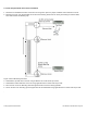
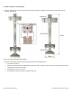
7. Position the GX and Bracket assembly so that the mounting brackets face the wall. Refer to “Side View” (top-left image)
and “Front View” (top-right image) shown in Figure 3-14.
8. Using the screw holes as a template, drill the required holes in the floor and wall (drill directly through the screw holes).
Refer to “Front View” (top-right image) and “Top View” (bottom-left image) shown in Figure 3-14.
Note: Eight M10 masonry bolts are required (not provided).
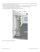
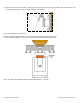
9. Insert masonry M10 bolts into drilled holes and tighten. Refer to Figure 3-15.
Figure 3-15.Location of Inserted Masonry Bolts